16 Pelco Manual C1402M-B (2/98)
3.4 CONNECTOR ASSEMBLY
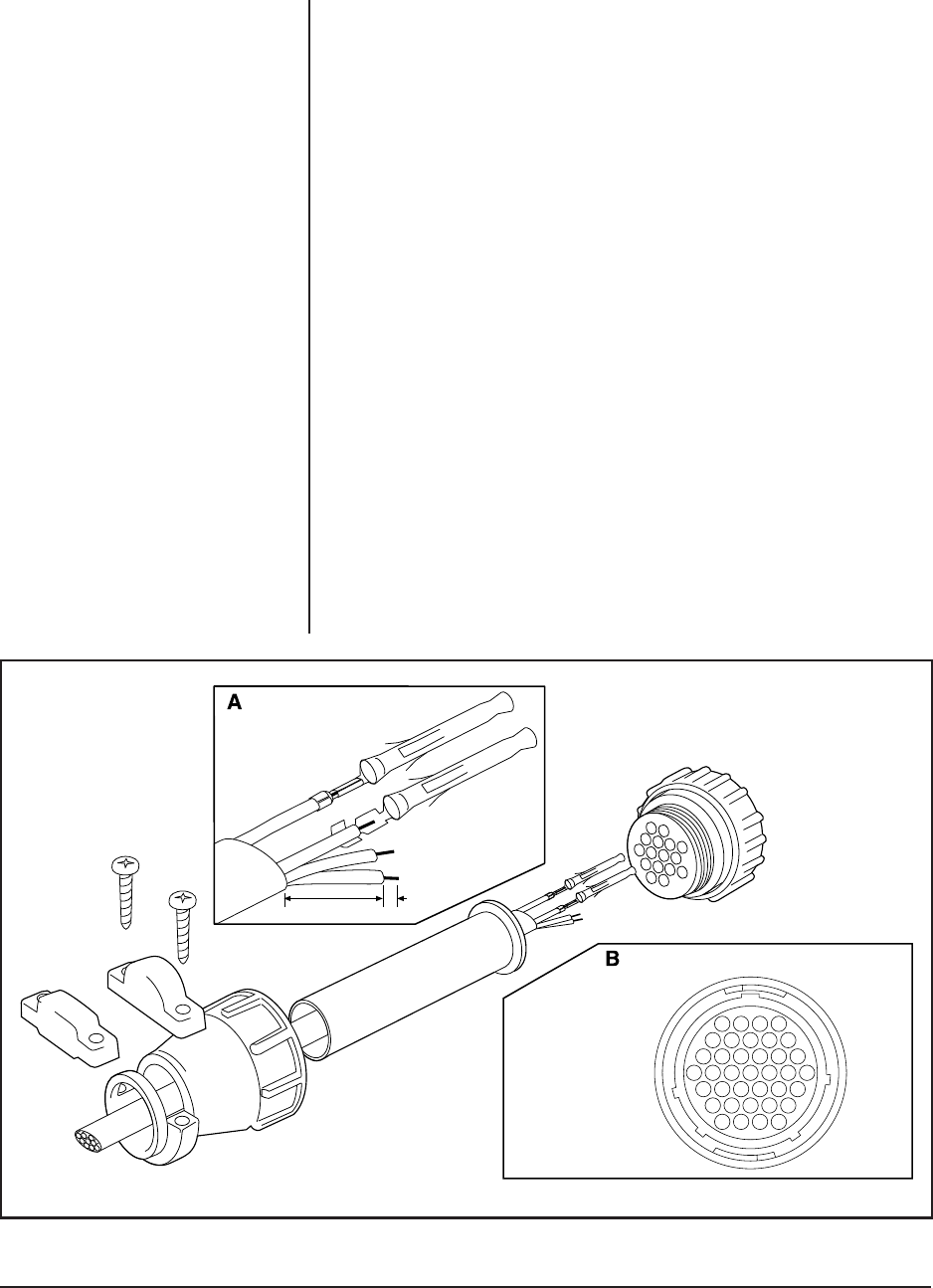
Assemble the connector parts according to the instructions below. Detail B, below,
reflects the pin arrangement specific to all SB26/SB2600 Series. Refer to Figure 10
during assembly. For best results use an AMP style crimper when making the wire
to pin connection.
The instructions that follow apply to all AMP style connectors regardless of pin size
or pin number.
1. Slide the connector clamp assembly over the conductor cable. If the diameter
of the conductor cable is such that the rubber boot will slide over it easily then
slide the rubber boot onto the conductor cable at this time. If not, discard the
rubber boot.
2. Prepare the wires from the conductor cable as follows:
a. Strip at least 1" from the cable jacket to expose the wires. You may need
to strip more from the cable jacket if you have more wires.
b. Strip 1/8" from each wire.
c. Using an AMP style crimper, crimp the wires and their insulation to the
connector pins. Refer to Detail A in Figure 10.
3. Slide the connector pins into the appropriate holes in the connector body until
they snap into place. Refer to Figure 10 for correct pin arrangement, depend-
ing on model and options.
4. Push the connector clamp assembly (with boot, if used) toward the connector
body. Screw the clamp assembly onto the connector body, being careful not to
disturb the wires.
5. To complete the assembly, attach the appropriate clamp with the screws pro-
vided and tighten.
OR
1"
1/8"
FRONT VIEW
Figure 10. Connector Assembly
14
59
15 10
22 16
28 23
33 29
37 34
37-PIN


