


Manual 2100-574
Page 5 of 23
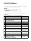
SPECIFICATIONS/FEATURES FOR
MD4000-B CONTROLLER
MD4000 Basic Controller
•Input power: 18-32 VAC, 60/50Hz, power is supplied from
A/C #1 and/or A/C #2
•Isolation circuitry: no line or low voltage phasing required
•Backup power: connection for -24 VDC or -48 VDC (-20 to
-56V) maintains microprocessor operation, front panel indication
& alarm relay operation during commercial power outages.
•Digital display: 4-character LCD
•Temperature display: F or C
•HVAC outputs: Form A (NO) relays (1A @ 24 VAC)
•Cooling control stages:
2 for each A/C unit (4 total)
•Heating Control stages:
1 for each A/C unit
•Operating temperature range: 0 to 120F (-18 to 49C)
•Storage temperature range: -20 to 140F (-29 to 60C)
•Temperature accuracy: +/- 1F from 60-85F (16-30C)
+/- 1% outside 60-85F
•Lead/lag changeover time: 0 to 30 days
•Timing accuracy: +/- 1%
•Inter-stage time delay: 10 seconds between stages
•On-Off differential: 2F (1C) is standard, 4F (3C) when
“excessive cycling” mode is enabled
•Comfort setting, Heating 68F(20C), for 1 hour
•Dead band (difference between cooling and heating set
points): 2F to 40F (1.1C to 22.2C)
•Fire/smoke interface: standard NC circuit jumper, remove
for connection to building system control, shuts down both
A/C units immediately
•Memory: EEPROM for set point and changeable
parameters (maintains settings on power loss)
•Space temperature sensors: 1 local is standard, will accept up
to 2 optional 25' remote sensors, Bard part number 8612-023.
When multiple sensors are used, temperatures are averaged
•Controller Enclosure: 20-gauge pre-painted steel, 9.25"W
x 20.875"H x 3.00"D, hinged cover, twenty four (24) .875"
diameter electrical knockouts
•LEDs for basic controller: Lead unit, Heating Stages 1 – 4
•Six (6) Push-button controls: On/Off switch-Change lead
unit-Increase & Decrease set points-Program/Save-Comfort.
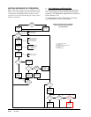
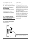
MOUNTING THE CONTROLLER
Included in the controller carton is the controller and
installation instructions.
The controller should be installed on a vertical wall
approximately four (4) feet above the oor-away from drafts &
outside doors or windows. Four (4) mounting holes are provided
for mounting to the wall and 7/8" holes for conduit connections
are provided in both the base, sides & top of the controller.
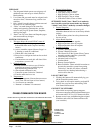
TEMPERATURE SENSORS
The standard (local) temperature sensor has 12" leads and
comes installed from the factory.
A secondary sensor is located internally on the main
controller board and serves as a reference and back-up
sensor to the local sensor. Any differential of +/- 12F
between the on-board and local sensor will cause the
controller to use the local sensor as its point of reference.
If the differential is greater than 12F then the controller
will check to determine the on-board sensor is reading a
temperature that is between the SP (set-point) plus 12F
and the SP minus the DB (dead-band) minus 12F. If it is
the on-board sensor will become the valid sensor reading
and the controller will ignore the local sensor reading. If
it is not then the controller will still use the local sensor
reading. This is to add additional level of operational
capability in the rare event the local sensor fails. If the
controller is operating in this mode it is indicated by the
lower left decimal point ashing in the display. Note: for
purposes of testing when the local sensor is manually
driven higher or lower by applying warm or cool water
to the probe the on-board sensor is inhibited for the rst
30-minutes following power up, or when power is cycled
off and back on.
The controller is designed to accept 1 or 2 additional
sensors and those have 25-foot leads. The Bard part
number for the optional sensor with 25-foot leads is
8612-023. These can be installed as required in the
structure to address hot spots, barriers to airow, etc.
It is recommended that the sensor lead wires be installed
in conduit for protective purposes.
The highest reading of any connected sensor will be
used for high temperature alarm and the lowest reading
sensor will be used for low temperature alarm.
TEMPERATURE SENSOR LOGIC
The standard local (LSEn) sensor monitors the
temperature at the controller location. If this is the only
sensor connected, it will control the temperature read-out,
the space (building) temperature, and also be used for
Low and High Temperature alarm functions.
If one or more REMOTE sensors are installed and
connected (Rem 1 or Rem 2), the temperature read-out
will display and the building will be controlled to an
average of all connected sensors. If there is more than
10F difference from the highest to the lowest connected
sensor, the actual control will be governed by the hottest
sensor for cooling and the coldest sensor for heating.
If multiple temperature sensors are used, the High and
Low temperature alarms will be governed by the average
of the connected sensors.
NOTE: All sensors are polarity sensitive. The copper
lead must connect to terminal CU, and the silver
lead to AG. Sensors are solid state, not RTD. Use
only sensors supplied by Bard. Sensor leads can be
extended up to 200 feet. Use 18-gauge twisted pair
with soldered connections.