


Manual 2100-574
Page 8 of 23
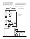
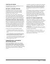
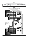
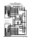
FIRE SUPPRESSION CIRCUIT
To disable the MD4000 and shut down both air
conditioners, terminals F1 and F2 may be used. The F1
and F2 terminals must be jumpered together for normal
operation. A normally closed (nc) set of dry contacts
may be connected across the terminals and the factory
jumper removed for use with a eld-installed re
suppression system. The contacts must open if a re is
detected. See appropriate connection diagram - Figures
1, 2 or 3 for this connection. Contacts should be rated
for pilot duty operation at 2 amp 24VAC minimum.
Shielded wire (22-gauge minimum) must be used, and
the shield must be grounded to the controller enclosure.
STAGING DELAY PERIODS
The following delays are built in for both cooling & heating:
Stage 1 – 0 seconds for blower (if not already on as
continuous)
10 seconds for cooling or heating output
Stage 2 – 10 seconds after Stage 1 for blower
10 additional seconds for cooling or heating
output
Stage 3 – 10 seconds after Stage 2
Stage 4 – 10 seconds after Stage 3
Note: For cooling Stages 1 and 2, the stage LED will
blink for 10 seconds while the cooling output is delayed
after that stage is called for. There is also a delay after
the stage is satised, and after the LED stops blinking,
the stage will turn off. There is a minimum 10-second
delay between stages 2 & 3, and 3 & 4, but no delayed
output when stage is turned on or off, and LED for
those stages will not blink.
BLOWER OPERATION
The controller can be congured to have main HVAC
blowers cycle on and off on demand; have all blowers
run continuously; or have the lead unit blower run
continuously with the lag unit blower cycling on
demand. Default setting is the blower on the lead unit
operates continuously. There is also an option to have
all blowers cycle on if one remote sensor is connected,
and a temperature difference of more than 5F between
any two sensors is observed. This helps to redistribute
the heat load within the structure and should reduce
compressor operating time.
When any of the stages are satised, the stage LED
will blink for ten (10) seconds before the stage is
actually turned off.
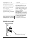
ADVANCE (SWAP) LEAD/LAG UNIT
FEATURE
Pressing the Advance button for one (1) second will
cause the lead and lag units to change positions.
This may be useful during service and maintenance
procedures. This function can also be done remotely by
closing a contact across the Advance terminals on the
main board.
ACCELERATE TIMER FEATURE
Pressing the UP arrow button for ve (5) seconds
will activate an accelerate (speed-up) mode, causing
the normal changeover time increments of days to
be reduced to seconds. Example: 7 days becomes
7 seconds. When “ACC” displays, release button.
Whichever LED is on, indicating lead unit will blink
over for each second until the controller switches. This
is a check for the timer functionality.