


Manual 2100-574
Page 7 of 23
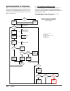
LOW VOLTAGE FIELD WIRING
The MD4000 is powered from the air conditioners that
it is controlling, 24 VAC (18-32V) low voltage only.
Circuitry in the MD4000 isolates the power supplies of
the two air conditioners so that no back feeds or phasing
problems can occur. Additionally, if one air conditioner
loses power, the MD4000 and the other air conditioner
are unaffected and will continue to operate normally.
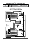
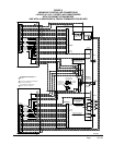
Connect the low voltage eld wiring from each unit
per the low voltage eld wiring diagrams in Section on
“Controller Wiring”. NOTE: Maximum of 18-gauge
control wiring should be used. Using heavier gauge
wiring can create excessive stress on the control board
as door is opened and closed. Create a wiring loop so
the door can open and close without stressing terminal
blocks.
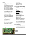
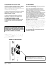
CONTROLLER GROUNDING
A reliable earth ground must be connected in addition
to any grounding from conduit. Grounding lugs are
supplied for this purpose.
CONTROLLER POWER-UP
Whenever power is rst applied to the controller, there
is a twenty (20) second time-delay prior to any function
(other than display) becoming active. This time-delay
is in effect if the controller On/Off button is used when
24VAC from air conditioners is present, and also if
controller is in “ON” position and 24VAC from air
conditioners is removed and then restored.
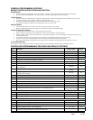
SPECIFICATIONS/FEATURES FOR
MD4000-B & -BC CONTROLLER ALARMS
Inputs
Lockout 1 2, 3 – input from HVAC #1
Lockout 2 2, 3 – input from HVAC #2
Outputs
Smoke/Fire Form C (SPDT)
Lockout 1 Form C (SPDT)
Refrigerant alarm HVAC #1
Lockout 2 Form C (SPDT)
Refrigerant alarm HVAC #2
Power Loss 1 Form C (SPDT)
Power loss HVAC #1
Power Loss 2 Form C (SPDT)
Power loss HVAC #2
Low Temp Form C (SPDT)
Low temperature alarm
High Temp 1 Form C (SPDT)
High temperature alarm #1
High Temp 2 Form C (SPDT)
High temperature alarm #2
Controller Form C (SPDT)
Controller failure alarm
Econ 1 E, F - Form A (NO)
See note (b)
Econ 2 E, F - Form A (NO)
See note (b)
2
nd
Stage (c) Form C (SPDT)
2
nd
-stage cooling alarm
(b) Make these connections to terminals E & F in HVAC 1
and 2 respectively if desired to have economizers open for
emergency ventilation at High Temp Alarm #2 setpoint
condition.
(c) For units with 2-stage compressors, 2nd stage cooling
alarm activates on cooling Stage 3 initiation.
2nd Compressor Form A (NC)
Dirty Filter Form A (NC)
4, 5 – Input from Unit
Economizer Fail Form A (NC)
8, 9 – Input from Unit