


Manual 2100-574
Page 6 of 23
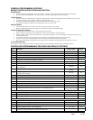
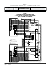
LOCATED IN THE MD4000 PANEL BOX
Unit #1 Terminal Block
R – 24VAC hot from Unit
C – 24VAC common from Unit
Y – Compressor Signal to Unit
F –
Economizer Shutdown Output to Economizer
A – Compressor Signal from Economizer
4 – Dirty Filter Alarm from Unit
5 – Dirty Filter Alarm from Unit
6 – Signal Common for F
8 – Economizer Fail from Unit
9 – Economizer Fail from Unit
10 – Emergency Vent Output to Economizer
41 – To Unit 2, 43
42 – To Unit 2, 44
43 – To Unit 2, 41
44 – To Unit 2, 42
45 – To Unit 2, 45 DCA Input
46 – To Unit 2, 46 DCA Input
47 – To Unit 1 Display
48 – To Unit 1 Display
Unit #2 Terminal Block
R – 24VAC hot from Unit
C – 24VAC common from Unit
Y – Compressor Signal to Unit
F –
Economizer Shutdown Output to Economizer
A – Compressor Signal from Economizer
4 – Dirty Filter Alarm from Unit
5 – Dirty Filter Alarm from Unit
6 – Signal Common for F
8 – Economizer Fail from Unit
9 – Economizer Fail from Unit
10 – Emergency Vent Output to Economizer
41 – To Unit 1, 43
42 – To Unit 1, 44
43 – To Unit 1, 41
44 – To Unit 1, 42
45 – To Unit 1, 45 DCA Input
46 – To Unit 1, 46 DCA Input
47 – To Unit 2 Display
48 – To Unit 2 Display
Gen Run/Econ Shutdown Terminal Block(a)
Gen Run Input
Economizer Fail Terminal Block
Alarm Output
Note: All alarm and output relays are dry contacts rated
1A @ 24 VAC.
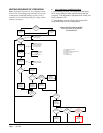
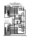
BASIC MD4000 CONTROLLER
INPUT/OUTPUT SPECIFICATIONS
MD4000 CONTROLLER CONNECTIONS
Located on Main Controller Board
Unit #1 C – 24VAC common
R – 24VAC hot
G – fan (Form A, NO)
W – heat (Form A, NO)
Unit #2 C – 24VAC common
R – 24VAC hot
G – fan (Form A, NO)
W – heat (Form A, NO)
F1-F2 Fire/smoke interface
Shipped with jumper installed (a)
48Vdc Back-up power input
-24Vdc or –48Vdc
-20V to –56V range
Local Main sensor, 12-inch leads
CU – copper, AG – silver
Polarity sensitive
Rem 1 Optional remote indoor sensor
CU – copper, AG – silver
Polarity sensitive
Rem 2 Optional remote indoor sensor
CU – copper, AG – silver
Polarity sensitive
H1-H2 Humidity controller input
Requires optional controller
Field installed
Advance Input used to remotely toggle lead/lag change
(a) These connections require either jumper or Normally
Closed (NC) relay contact at the Fire/Smoke and Generator
interface for Controller to function.
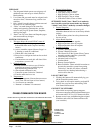
Alarm relays can be wired for NO (close on alarm) or NC (open on alarm) strategy. Alarm relays can be used individually if
there are enough available building alarm points, or can be arranged into smaller groups or even a single group so that all
alarm capabilities can be utilized. When multiple alarms are grouped together and issued as a single alarm there will be no
off-site indication of which specic problem may have occurred, only that one of the alarms in the group has been triggered.
The individual alarm problem will be displayed on the LED display on face of the controller.
NOTE:
Sensors are
solid state,
not RTD.
Use Bard
sensors only.
Note: All alarm relay outputs have 10-second delay
before issuing to protect against nuisance alarm signals.