


29
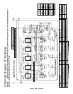
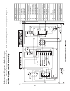
Code Description
BRE Broiler elements
BSB Broiler switch block
BTC Broiler controller
CFM Cooling fan motor
IGS Ignition switches
ISG Ignition spark generator
LBE Left hand bottom element
LFE Left hand fan element
LTI Left hand top inner element
LTO Left hand top outer element
LOS Left hand oven switch block
NLI Neon indicator light
OFM Oven fan motor
OLS Oven light switch
OTL Left hand oven thermostat
OTR Right hand oven thermostat
OVL Oven light bulb
ROE Right hand oven element
RSB Right hand oven switch
block
TCK Timer clock
TCO Thermal cut out
L2 L2 Supply (Red)
N Neutral Supply (White)
L2 L1 Supply (BlacK)
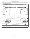
Schematic diagram of the Range
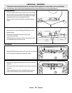
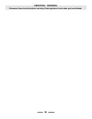
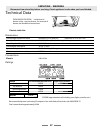
Caution: Label all wires prior to disconnection when servicing controls. Wiring errors can cause improper and dangerous
operation. Verify proper operation after servicing.