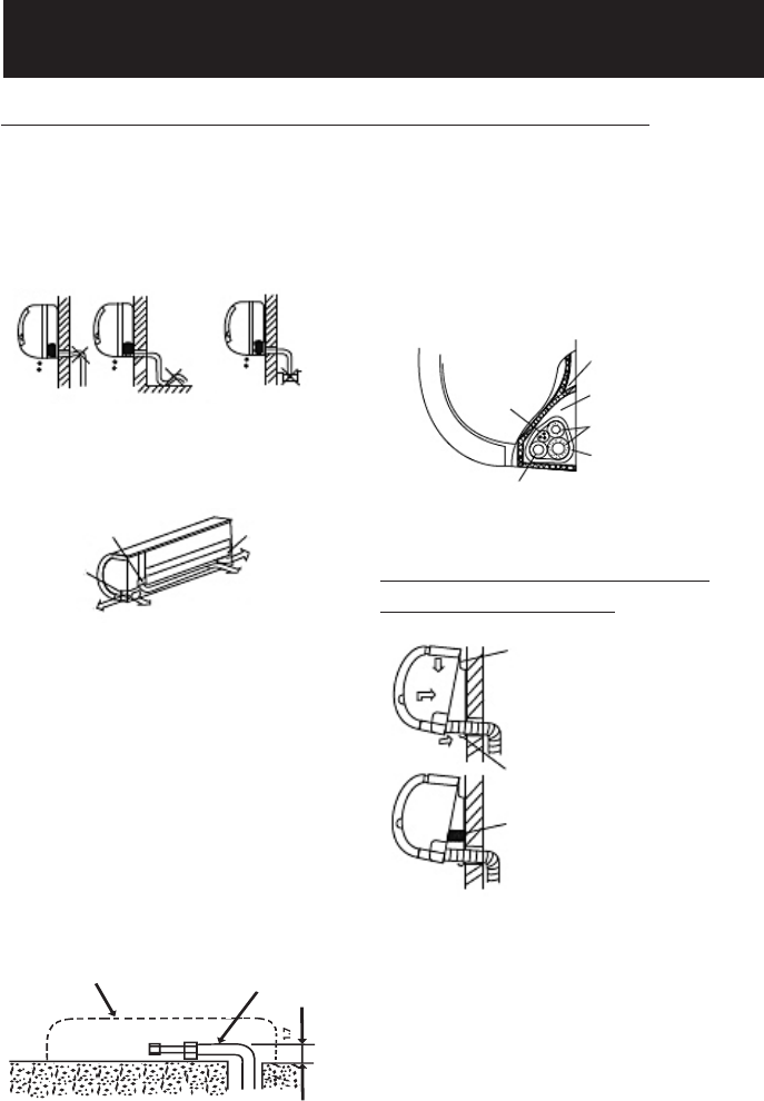
i) Drainage
Run the drain hose downward.
Do not install the drain hose as illus-
trated below.
Do not form a rise
Do not put the hose
end into water
a) For the left-hand and right-hand piping,
remove the pipe cover from the side panel.
Explain to the customer that the pipe cover
must be kept as it may be used if the air
conditioner is moved to another location.
b) For the left-hand and rear-left-hand pip-
ing, install the piping as shown. Bend the
connective pipe to be
placed at a height of 1 5/8 inches
or less from the wall.
ii) Connective Pipe
Pipe holder
Pipe cover
Right piping Right back piping
Pipe Cover
Left back piping
Left piping
2) Connective Pipe and Drainage Installation
c) Fix the end of the connective pipe.
(Refer to Tightening Connection in
Refrigerant Piping Connection).
Connective Pipe
Evaporator (Indoor) Unit outline
iii) Piping and Bandaging
Connective Cable
Ponding Box
Pipe Room
Connective Pipe
Wrapping Belt
Drain Hose
Wind the Connective cable, drain hose
and wiring tape securely, evenly as
shown below.
Evaporator (Indoor) Unit
i) Pass the piping through
the hole in the wall
ii) Put the upper claw at
the back of the installation
plate, move the evaporator
(indoor) unit from side to
side to see if it is securely
hooked.
iii) Insert a spacer between the evaporator
(indoor) unit and the wall bracket to sepa-
rate the bottom of the unit from the wall.
iv) Push the lower part of the evaporator
(indoor) unit up on the wall. Then move
the evaporator (indoor) unit from side to
side, up and down to check if it is hooked
securely.
3) Evaporator (Indoor)
Unit Installation
EVAPORATOR INSTALLATION (INDOOR)
“
9


