


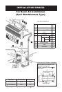
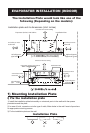
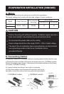
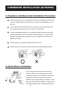
CONDENSOR INSTALLATION (OUTDOOR)
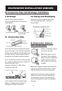
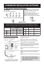
3) Refrigerant Piping Connection
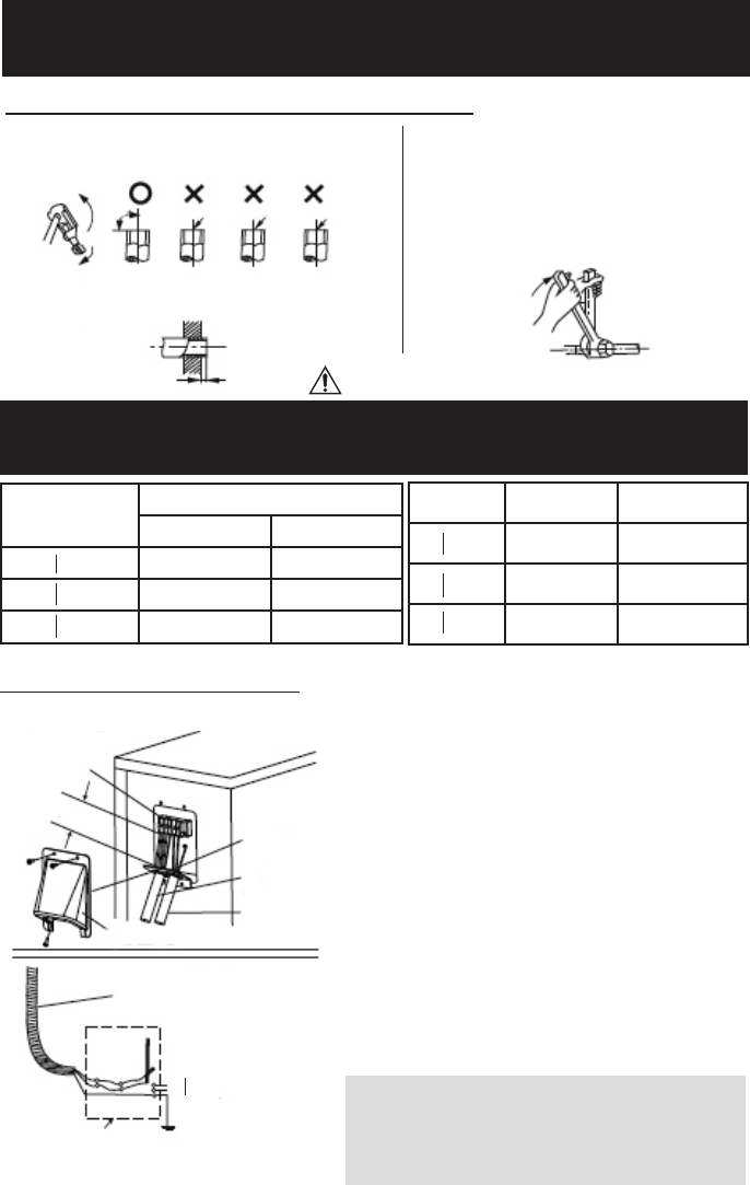
i) Flaring
ii) Tightening Connection
Cut a pipe with a pipe cutter
Insert a flare nut into a pipe and flare the pipe
Align pipes to be connected.
Sufficiently tighten the flare nut with
fingers, and then tighten it with a
spanner and torque wrench as shown.
Outer Diameter (inches)
A (inches)
Max. Min.
O 1/4 0.5 0.028
O 3/8 0.6 0.04
O 1/2 0.7 0.04
Excessive torque can break the flare nut and cause a leakage of refrigerant.
* Ensure the refrigerant pipe is firmly attached before running the compressor.
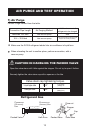
CAUTION
Outer Diameter
Tightening Torque
(N. inches)
Additional Tightening
torque (N. inches)
O 1/4
11.57 ft lbs
(160kgf.cm)
14.45 ft lbs
200kgf.cm)
O 3/8
21.7 ft lbs
(300kgf.cm)
25.30 ft lbs
(350kgf.cm)
O 1/2
36.14 ft lbs
(500kgf.cm)
39.75 ft lbs
(550kgf.cm)
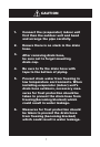
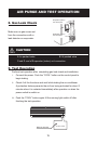
Note: To prevent wires from loosen-
ing or leaving the Cord Clamp, please
select proper cord diameter to fill the
holes on the cord clamp
i) Remove the cover control from the unit by
loosening 3 screws.
ii) Dismount caps on the conduit panel.
iii) Temporarily mount the conduit tubes
(not included) on the conduit panel.
iv) Properly connect both the power supply
and low voltage lines to the corresponding
terminals on the terminal block.
v) Ground the unit in accordance with local
codes.
vi) Be sure to size each wire allowing several
inches longer than the required length for
wiring.
vii) Use lock nuts to secure the conduit tubes.
4) Wiring Connection
Special Branch Circuit Breaker
(Fuse/Breaker capacity: 20A)
Condensor (Outdoor) Unit
Terminal block
Over 1.7”
Conduit panel
Connecting
cable
Power
supply
cord
Cover Control
Power supply cord
Power supply
115V - 60Hz
12