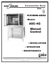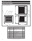
Gas Convection Oven - Manual Control
Pg. 5.
G A S S U P P LY & I N S T A L L A T I O N
INSTALLATION REQUIREMENTS
G
AS CONNECTION
: 3/ 4" NPT
C
HECK PLUMBING CODES FOR PROPER SUPPLY LINE
SIZING TO ATTAIN BURNER MANIFOLD
NOTE: If a flexible gas line is used, it must
be AGA approved, commercial type
a
nd at least 1" I.D.
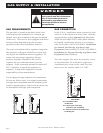
GAS PRES S U R E CHART
The gas valve and burner have been fitted
according to the gas type specified on the
identification name plate.
TECHNICAL SPECIFICATIONS
N a t u r a l G a s
Min. connected pressure 7.0" W.C. 1.74 kPa
Max. connected pressure 14.0" W.C. 3.48 kPa
Orifice Size #26
Manifold pressure 5.0" W.C. 1.25 kPa
Gross thermal output
50,000 Btu/hr
Propane Gas
Min. connected pressure 11.0" W.C. 2.74 kPa
Max. connected pressure 14.0" W.C. 3.48 kPa
Orifice Size #43
Manifold pressure 10.0" W.C. 2.49 kPa
Gross thermal output
50,000 Btu/hr
GAS SPECIFICATIONS
FIELD CONVERSION OF FUEL TYPE
To convert from either fuel type, replace the orifice
located at the burner inlet with the desired orifice.
Set the manifold pressure to the corresponding
values located in the following table. The pressure
tap is located at either the lower elbow of the gas
train, below the main
ON/ OFF valve or in the pipe
near the regulator.
FUEL TYPE ORIFICE SIZE ORIFICE P/N MANIFOLD PRESSURE
Natural # 26 OR-26431 5.0 IN/WC
Propane # 43 OR-26430 10.0 IN/WC
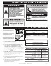
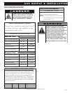
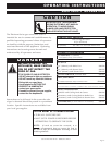
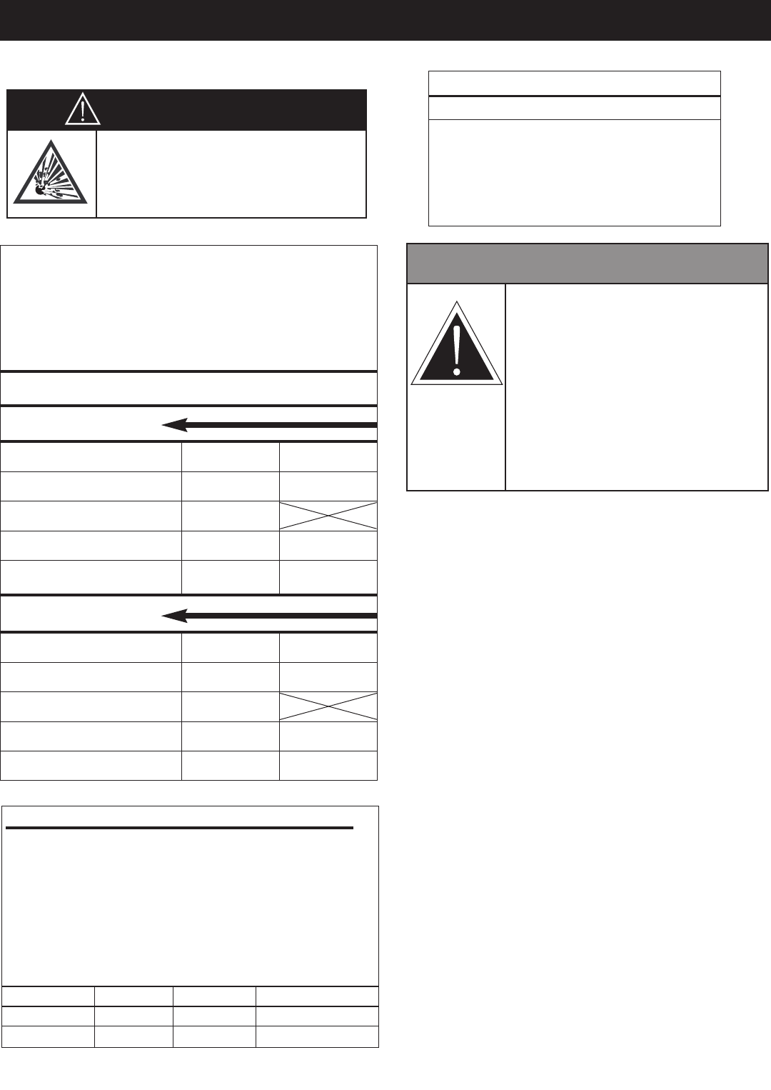
D A N G E R
CONNECTING TO THE WRONG GAS
SUPPLY COULD RESULT IN FIRE OR
A
N EXPLOSION CAUSING SEVERE
INJURY AND PROPERTY DAMAGE.
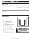
W A R N I N G
TO AVOID SERIOUS PERSONAL
INJURY, installation of this appliance
must conform to local, state, and
national codes; the current edition of
the American National Standard
Z223.1, National Fuel Gas Code, and
all local municipal building codes. In
Canada, installation must be in
accordance with Standard CAN/CSA
B 149.1 and Installation Codes - Gas
Burning Appliances, and local codes.


