Troubleshooting Procedures
RS2420002 Rev. 5 16
CAKH and AKH Units
Halogen Element Continuity Test
1. Disconnect power from cooktop. Connect ohmmeter
leads to element assembly terminals. Note that the
resistive element is in series with halogen tubes.
2. Check for continuity readings on the follow elements
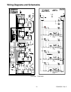
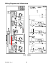
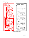
as indicated in the appropriate wiring diagram.
Performance Test
1. Set meter to read at least 250 volts. Connect meter
leads to element assembly tabs.
2. Connect cooktop to power supply.
3. Test element with no load (no pan on burner) turn
corresponding surface control to HIGH.
4. While element is heating, observe voltage and
element. The halogen glass tubes should light up
immediately. Voltage should indicate 240 VAC, if not
replace element.
5. Using an infinite switch, after a delay of approximately
one minute the high temperature limit switch will open
and line voltage is turned off to the element. Voltage
on meter will indicate 0. Observe two complete cycles
before turning surface control to OFF position.
Halogen Element and Quick Star Elements
High Temperature Limit/Hot Light Switch
1. The HTL switch should not open until the temperature
of the glass tube reaches approximately 1200°F.
2. The hot light switch close’s when temperature of the
glass tube reaches approximately 145°F.
3. Do not attempt to adjust these switches. If they have
failed, replace the switch.
4. If the glass tube or the heat sensitive wire is broken,
replace the switch. Do not touch glass tube, residual
skin oil can premature failure.
Quick Star Elements
−
Power Disconnected
Small Element Continuity Test
1. Disconnect power from cooktop. Connect ohmmeter
leads to element terminals.
2. Meter should indicate continuity.
Large Element Continuity Test
1. Disconnect power from cooktop. Connect ohmmeter
leads to element terminals.
2. Meter should indicate continuity.
Quick Star Elements
−
Power Connected
Performance Test
1. Set meter to measure at least 250 VAC. Connect
meter leads to element tabs.
2. Connect cooktop to power source.
3. Test element with no load (no pan on burner), turn
corresponding surface control to HI. Voltage should
indicate 240 VAC.
4. Element should glow after a few seconds. If it does
not glow check element resistance or continuity to
high limit/ hot light assembly.
5. While element is heating, observe voltage and
element. Voltage should indicate 240 VAC.
6. After a delay of approximately six minute
(±30 seconds), the high limit switch will open its
contacts and turn power off to the element. Observe
two complete cycles prior to setting surface control to
OFF position.
AKE Units
−
Solid Disk Elements
Continuity Test−Power Disconnected
1. With power disconnected, connect meter leads to the
element assembly terminals.
Large Element = indicates continuity
Small Element = indicates continuity
2. If no continuity is measured replace element.
Performance Test−Power Connected
1. Set meter to measure at least 250 VAC. Connect
meter leads to element tabs.
2. Connect cooktop to power source.
3. Test element with no load (no pan on burner), turn
corresponding surface control to HI. Voltage should
indicate 240 VAC.
4. Element should heat after a few seconds, check
element and thermal switch for continuity.
5. After a delay of approximately six minute
(±30 seconds), the elements internal limit switch
drops power consumption to 500 watts. This protects
the solid disk from being warped.
6. If the element is left on high with no load for
approximately 30 minutes or more, the thermal switch
will cycle on and off.


