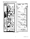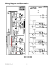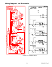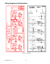
Troubleshooting Procedures
RS2420002 Rev. 517
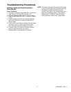
Indicator Lights and Diode Assembly
−
Some Models
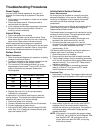
Power Connected
1. Set meter to measure at least 250 VAC. Connect one
meter lead to P of control and the other to L2.
2. Connect cooktop to power source. Turn on control.
3. Meter should indicate 240 VAC. If it does not, replace
control.
4. If meter indicates 240 VAC and indicator does not
light, move lead from P of control to terminal D of
terminal block.
5. If meter does not indicate any voltage, then the diode
is an open circuit or a wire harness has a broken
wire. Test diode and wire harness for continuity.
6. If a short exists in the diode, all indicator lights will
come on when one control is turned on.
7. Replace diode or light assembly as required.
NOTE:
Test diode, disconnect wires and connect meter
on 10 KΩ scale. Meter should indicate continuity
with leads connected one direction and no
continuity with leads in the reverse direction for a
diode to be operating properly. If no continuity,
diode is open. If continuity in both directions,
diode is shorted. In either case, replace diode.


