


INSTALLATION
8
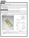
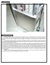
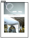
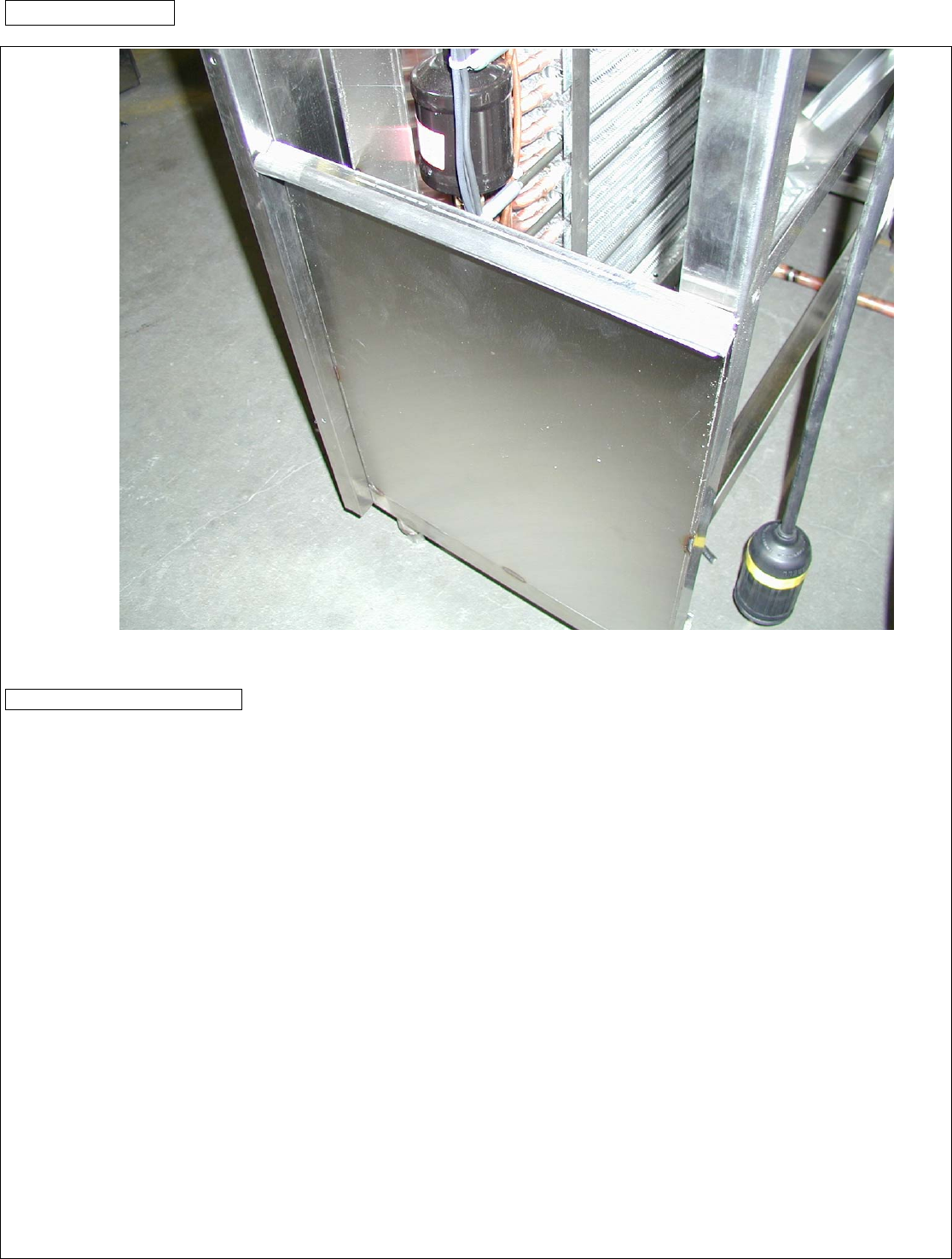
PHOTO #3
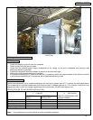
B.2.3. Electrical Connections
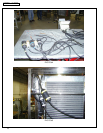
All power cables inside the cabinet, with the exception of door / window heater and door switch cables (see
PHOTO #4, page 10), are provided with twist and lock plugs and connectors. All cables, plugs, and connectors are color
coded (see Color Code Chart on page 9). Connect the plugs and connectors of the same code color (see PHOTO #5,
page 10).
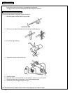
According to the color code chart, the orange coded cable is for the door / window heater. Connect this cable with
the door and window heaters inside the connection box provided by the box supplier. Connect the brown cable with the
door switch using heat shrink butt splices.
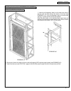
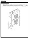
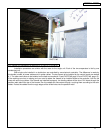
The thermocouple cables (gray) are provided for the air probe(s), food probe(s), and defrost probe. Connect the red,
yellow, green, and blue cables in the terminal block on the top of the evaporator assembly (see PHOTO #6, page 11). The
brown cable is for the air probe located behind the top fan. The white cable is for the defrost probe located on the bottom
of the evaporator. Use heat shrink butt splices. Hang all cables so they will not touch the defrost heaters and will not be
caught by the fan blades. Install the thermostat bulb on the coil assembly frame as close to the defrost heaters as possible
but not closer than 5”. Secure the bulb of the thermostat with cable ties to minimize risk of breakage of the capillary tube
caused by vibration.
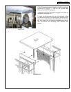
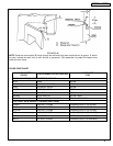
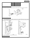
NOTE: If the door switches are not installed by the box supplier, mount the ones provided by American Panel
Corporation as shown on page 9, DRAWING #6 and page 12, PHOTO #7.