


AD9843A
–6–
REV. 0
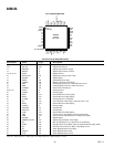
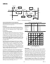
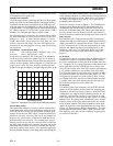
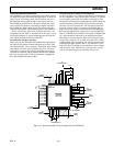
PIN CONFIGURATION
36
35
34
33
32
31
30
29
28
27
26
25
13 14 15 16 17 18 19 20 21 22 23 24
1
2
3
4
5
6
7
8
9
10
11
12
48 47 46 45 44 39 38 3743 42 41 40
PIN 1
IDENTIFIER
TOP VIEW
(Not to Scale)
AUX1IN
AVSS
AUX2IN
AVDD2
BYP4
NC
CCDIN
(LSB) D0
D1
D2
D3
D4
NC = NO CONNECT
D5
D6
D7
D8
BYP2
BYP1
AVDD1
AVSS
AD9843A
(MSB) D9
AVSS
SCK
SDATA
SL
NC
STBY
NC
THREE-STATE
DVSS
DVDD2
VRB
VRT
CML
DRVDD
DRVSS
DVSS
DATACLK
DVDD1
DVSS
PBLK
CLPOB
SHP
SHD
CLPDM
DVSS
DRVSS
DRVSS
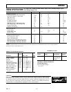
PIN FUNCTION DESCRIPTIONS
Pin Number Name Type Description
1, 2 DRVSS P Digital Driver Ground
3–12 D0–D9 DO Digital Data Outputs
13 DRVDD P Digital Output Driver Supply
14 DRVSS P Digital Output Driver Ground
15, 18, 24, 41 DVSS P Digital Ground
16 DATACLK DI Digital Data Output Latch Clock
17 DVDD1 P Digital Supply
19 PBLK DI Preblanking Clock Input
20 CLPOB DI Black Level Clamp Clock Input
21 SHP DI CDS Sampling Clock for CCD’s Reference Level
22 SHD DI CDS Sampling Clock for CCD’s Data Level
23 CLPDM DI Input Clamp Clock Input
25, 26, 35 AVSS P Analog Ground
27 AVDD1 P Analog Supply
28 BYP1 AO Internal Bias Level. Decoupling
29 BYP2 AO Internal Bias Level Decoupling
30 CCDIN AI Analog Input for CCD Signal
31 NC NC Leave Floating or Decouple to Ground with 0.1 F
32 BYP4 AO Internal Bias Level Decoupling
33 AVDD2 P Analog Supply
34 AUX2IN AI Analog Input
36 AUX1IN AI Analog Input
37 CML AO Internal Bias Level Decoupling
38 VRT AO A/D Converter Top Reference Voltage Decoupling
39 VRB AO A/D Converter Bottom Reference Voltage Decoupling
40 DVDD2 P Digital Supply
42 THREE-STATE DI Digital Output Disable. Active High
43 NC NC May be tied High or Low. Should not be left floating.
44 STBY DI Standby Mode, Active High. Same as Serial Interface Standby Mode
45 NC NC Internally Not Connected. May be Tied High or Low
46 SL DI Serial Digital Interface Load Pulse
47 SDATA DI Serial Digital Interface Data
48 SCK DI Serial Digital Interface Clock
TYPE: AI = Analog Input, AO = Analog Output, DI = Digital Input, DO = Digital Output, P = Power.