SERVICE
CLEARANCE
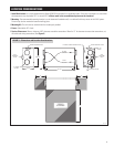
12"
12"
36"
37-7/16"
20-9/16"
CEILING MOUNTING HOLES
CEILING MOUNTING HOLES
ON / OFF
SWITCH
WALL
MOUNTING
HOLES
WALL
MOUNTING
HOLES
RETURN
STALE AIR
SUPPLY
FRESH AIR
EXTERNAL CONTROL WIRING ACCESS
6" ROUND COLLARS
12-3/4"
6" ROUND
COLLARS
2"
2"
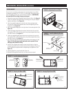
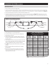
FIGURE 3 – Dimensions and Location Considerations
90-1743
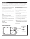
LOCATION CONSIDERATIONS
1. Install Unit Indoors: It is recommended that the Model 8100 ERV be mounted in a conditioned space. If the unit is mounted in an area where
the temperature may drop below 32°F or exceed 100°F, all duct work in the unconditioned space must be insulated.
2. Mounting: The recommended mounting location is on the basement foundation wall, or a stud wall with easy access to the HVAC system.
The unit may also be mounted to basement ceiling joists.
3. Mounting Kit: The unit must be mounted with the mounting kit provided.
4. Power: Outlet within 30” of unit.
5. Service Clearances: Allow a minimum of 36” clearance around the access door. Allow for 12” of clearance to access duct connections, on/
off switch and wiring connections. (See Figure 3.)
3


