


MECHANICAL INSTALLATION (CONTINUED)
BALANCING THE SYSTEM
DUCTING (CONTINUED)
EQUIPMENT REQUIRED
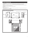
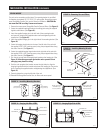
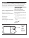
•Theintakeandexhausthoodsmustbelocatedatleast10ft.
apart to avoid cross contamination. (See Figure 18.)
•Intakeandexhausthoodsshouldbeabovetheexposedsnow
line or a minimum of 18” above ground level, whichever is
greater. (See Figure 18.)
•Theintakehoodshouldbeaminimumof10ft.fromanappliance
vent that exhausts toxic fumes. The hood should not be installed
near sources of pollution and/or extreme temperatures, such as
furnace exhaust, car exhaust, dryer vents, etc.
•DonotconnecttheERVexhausttoanygasapplianceflue.
•Donotconnecttheexhaustoutletintoanattic,storageorgaragespace.Excessmoisturecoulddevelopintheseareas,possiblycausing
damage to the home.
•Ifnotrunningcontinuously,afieldsuppliedbutterflydampermustbeinstalledintheintakeductnearthehood.(SeeFigure 17.)
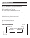
DUCT WORK CONNECTIONS WITHOUT FORCED AIR
•Alltheductingconnectionproceduresapply,withtheexceptionofthefollowingchanges:
•Thefreshairsupplycanbeductedtovariouspartsofthehome,wherefreshairisneeded.
•Itisrecommendedthatnomorethan3freshairsupplyductsbeusedtoassureadequateairflow.
•Thetotalfreeareaofsupplygrillesshouldnotbelessthan75in
2
. For example: Three supply ducts would require a minimum of 25 in
2
of free
area each.
•Donotplaceasupplyoutletinthesameroomorinthevicinityofthestaleairreturnfromthehouse.
•Itisrecommendedthatthefreshairsupplybeinahallorfoyertoavoiddraftsandblowernoiseinoccupiedareas.
In order for the ERV to perform effectively, the volume of fresh air supplied to the house must match the volume of stale air exhausted. Because the
duct work in the two airstreams will most likely be different, the system must be balanced. Balancing is accomplished by installing dampers in both
airstreams, measuring the airflow, and dampering down the airflow in the stream with the highest flow, until the airflow in both streams is the same.
The following procedure is the recommended method. Other measuring instrumentation may be used if it is accurate enough to balance the
airflow in the supply and exhaust streams to within 10% of each other.
•TwoDwyerMagnahelicDifferentialPressureGauges;Series2000,0-0.25”w.c.(orequal).Note:Donotuseastandarddifferentialpressure
gauge that reads above 0.25” w.c. The reading will not be accurate for the airflow required by the ERV.
•TwoResearchProducts’airflowmeasuringdevices,PartNumber5158.
•3/16”IDflexibletubing.
•Drillwith7/8”bit.
Before balancing the system, verify the following:
1. Make sure the EnergyMax Transfer Core and filters are installed correctly.
2. Check all duct work connections to be sure they are installed and sealed properly.
3. Fasten door securely to housing.
4. Place all dampers in the fully open position.
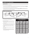
GROUND
10 FT MINIMUM
18 INCHES
MINIMUM
INTAK
EE
XHAUST
FIGURE 18 – Intake and Exhaust Hoods
90-1748
8