


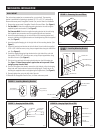


5 FT. MIN.
5 FT. MIN.
2-1/2 FT2-1/2 FT
PRESSURE GAUGES
STALE AIR
FROM HOUSE
FRESH AIR
FROM OUTSIDE
FRESH AIR
TO HOUSE
STALE AIR
TO OUTSIDE
AIR FLOW MEASURING
DEVICE #5158
AIR FLOW MEASURING
DEVICE #5158
DAMPER
DAMPER
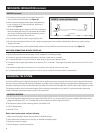
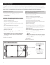
FIGURE 19 – Set-up for Balancing Airflow
90-1746
BALANCING THE SYSTEM (CONTINUED)
BALANCING AIRFLOW
1. Drill a 7/8” hole in the return and supply ducts.
2. Install the two airflow measuring devices in the duct using the drilled holes and seal with tape. Verify the airflow arrows are pointed in the
direction of airflow. The measuring devices should be a minimum of 2-1/2’ from the damper in a 5’ section of straight duct. (See Figure 19.)
3. Set up the pressure gauges so that they are vertical and level and adjust to zero.
4. Connect the tubing from the airflow measuring devices in the ducts to the pressure gauges (see Figure 19). The high pressure tap on the
airflow measuring device must be connected to the high pressure tap on the pressure gauge. Similarly, connect the low pressure tap on the
measuring device to the low pressure tap on the pressure gauge.
5. Verify the dampers are in the fully open position.
6. Turn off the HVAC system blower and any other exhaust fans.
7. Plug in and turn on the unit.
8. Read the pressure gauges. If the gauge readings are the same,
the system is balanced and does not require further adjustment.
Proceed to Step 10.
9. If the readings are different, slowly close the damper on the duct
with the higher gauge reading until the two readings are identical.
When the readings are the same, the system is balanced.
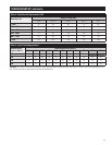
10. See Table 1 for approximated airflow based on pressure gauge
readings.
11. Secure the damper positions to prevent them from changing
during operation.
12. Disconnect the tubing and pressure gauges and remove the
airflow measuring devices. Seal the duct openings where the
measuring devices were located.
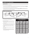
Table 1 – Airflow Approximations
Airflow in a 6” Duct as Measured using
Airflow Measuring Device #5158
Gauge
Readings
(in. w.c.)
Airflow
(cfm)
Gauge
Readings
(in. w.c.)
Airflow
(cfm)
0.005
30
0.065 119
0.010
44
0.070 124
0.015
55
0.075 128
0.020
64
0.080 132
0.025
72
0.085 137
0.030
80
0.090 141
0.035
86
0.095 145
0.040 93 0.1 149
0.045 98 0.105 152
0.050 104 0.110 156
0.055 109 0.115 160
0.060 114 0.120 163
NOTE: If airlow is restricted by more than 20% (see bold values in
Table 1), check ductwork and connections to increase flow.
9