


Operator Manual –XR Series Crossovers Page - 5
All Rights Reserved
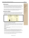
XR Crossovers
Ashly crossovers are based upon a powerful state-variable filter circuit, which guarantees
that two adjacent frequency band outputs always remain in phase. These crossovers offer a
number of useful and unusual features, including continuous tuning, a response control, and
a unique output stage, which maintains low noise at any level setting. The models also
include a 200:1 tuning range, output mute switches, and both TRS and XLR connectors.
Like other Ashly products, your crossover features low noise and distortion, active balanced
inputs, a peak level indicator, a precision regulated power supply, protection against
abnormal input or output conditions, and rugged mechanical construction
Connectors & Cables
The outputs are low impedance (100 ohms typical) servo-balanced using either connector. A
servo-balanced output stage simulates a true transformer output to allow interfacing with
virtually any type of load. For maximum headroom, terminate outputs into loads of 600
ohms or greater.
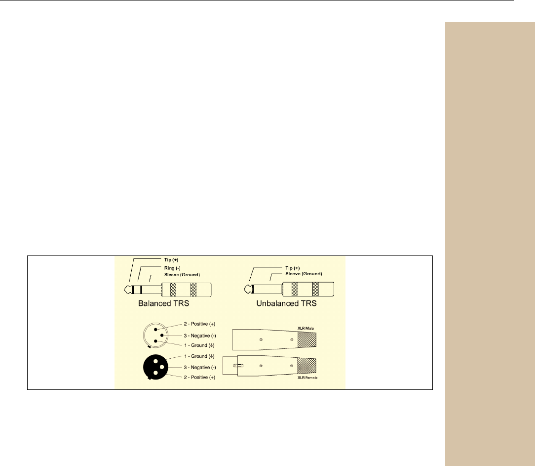
XR Connector Polarities
Unbalanced Connections and Grounding
If you must use unbalanced connectors, the negative lead of the connector should be tied to
the ground lead. Using unbalanced connections could result in chassis ground-loop noise.
Altering the signal/chassis ground relationship in equipment connected to your MQX unit
may eliminate the noise.
Inputs
Inputs are 20K active balanced, or 10K unbalanced. The inputs of all Ashly crossovers
are in phase with the outputs.
Outputs
The outputs are low impedance (200 typical) pseudo-balanced using either connector.
Pseudo-balanced lines have an equivalent line impedance on both (+) and (-) lines,
allowing for long cable runs without compromising common mode rejection of unwanted
noise. For maximum headroom, terminate outputs into loads of 600 or greater.
Each model has an additional output labeled MONO LOW OUT. This output represents
the sum of low frequency outputs of both channels, for driving mono sub-woofers in a
stereo system, reducing the number of power amps needed.
Safety Instructions – 3
Introduction – 4
XR Crossovers – 5
Connectors & Cables – 5
Unbalanced
Connectors
Inputs
Outputs
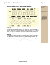
Physical Description - 6
Installation – 7
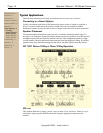
Typical Applications - 8
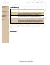
Troubleshooting - 10
Dimensions - 10
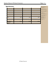
Specifications - 11
Warranty - 12