


Page - 6 Operator Manual – XR Series Crossovers
Copyright© 2006 – Ashly Audio Inc.
Physical Description
The XR-1001 is 1RU, and weighs 8 pounds. The XR-2001 & XR-4001 are 2RU, and weigh 11 pounds.
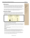
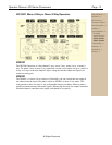
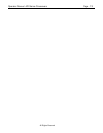
XR-1001 & XR-4001 Front Panels
1. Power - There is a dedicated power LED on the front;
the power switch is on the back of the unit.
2. Input Level - boosts incoming signal up to +8dB
before it reaches the filters, or attenuates the signal to
off. Maximum input level is +23dBu. The “U” shown at
the 12:00 position indicates “unity gain.”
3. Crossover Frequency - This infinitely variable control
allows you to select an appropriate crossover point.
Clockwise turning raises the crossover frequency
while counterclockwise lowers it. Frequencies are
marked on standard ISO 1/3 octave center
frequencies with each octave calibrated. Calibration
accuracy is typically within 1/3 octave or better. If
greater accuracy is necessary, measure the actual
crossover frequency with an external device.
To allow a wider tuning range, the crossovers use a
recessed range switch for each frequency control.
LED indicators provide range status at power-on. The
range switch divides the frequency indicated on the
frequency control by 10 and gives a total range of
200:1. Avoid damage to speakers by muting the
outputs before changing the range switch.
4. Response - adjusts the damping of the filter affecting
the response shape at the crossover point. The dial
calibrations refer to the amount of attenuation effected
by the filter at the crossover frequency, i.e., a setting
of 3dB means that the filter’s high-pass and low-pass
outputs are each “rolled off 3dB at the crossover
point”. This describes Butterworth filter response, or a
gentle 3dB peak at the crossover point where the two
filter output signals overlap. To obtain a flat signal, or
“Linkwitz-Riley” response, set the Response control to
“6”. To obtain a notch at the crossover point, turn
down the response control past “6” to best suit your
needs. The purpose of this control is to help offset the
inaccuracies inherent in typical loudspeakers, helping
you to achieve a flat system response. NOTE: The
Response control is not a “slope” control. The
Response control only affects filter response shape in
the immediate vicinity of the crossover frequency; the
ultimate crossover slope is a fixed parameter.
5. Output Level - The output stage operates at unity gain with
the output level controls set at “U”. Max gain of the output
stage is +15dB. In a typical setup, power amplifier input
level controls should be run “full-on”, with level control being
accomplished at the crossover. Note that horn and
compression driver combinations are much more efficient
than cone speakers, often by 12 to 20dB. When used
together, you should expect a much lower level setting for
the horns to obtain proper balance. Output mute switches
allow you to isolate individual or grouped outputs for
listening tests without affecting the settings of any other
outputs.
6. Clip Indicator - Ashly crossovers feature a peak detection
which monitors signal level at several critical points. The
LED will flash when signal levels of +20dBu are reached
anywhere in the crossover. Since our crossovers have a
nominal 23dB of headroom referenced to a standard
operating level of 0dBu (.77 Volts), a flashing LED warns
you that you are only 3dB from clipping. Since peak levels
are monitored at several points, the clip LED can be used to
isolate the source. If the LED flashes even though all input
and output levels are turned down, the signal feed is
excessive. If the LED flashes when you turn the Input level
control up (with the outputs still turned down), the overload
is occurring in the filter sections, and you should back the
Input level down a bit. If the LED first flashes when you turn
the output level controls up, then the overload is occurring
in the output stage. In this case, if your power amplifier
controls are at full gain, you are probably severely
overdriving your amplifier.
Safety Instructions – 3
Introduction – 4
XR Crossovers – 5
Connectors & Cables–5
Physical Description – 6
Front Panels
Rear Panels
Installation – 7
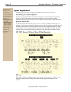
Typical Applications - 8
Troubleshooting - 10
Dimensions - 10
Specifications - 11
Warranty - 12
CAUTION: High frequency
compression drivers may be
destroyed by the use of too low
a crossover frequency. Make
sure the range switch is
p
roperly set. You may want to
install a security cover if the
unit is accessible to untrained
p
eople.