


3
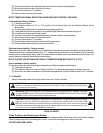
For a single unit: Refer to Figure 4
(1) Tilt Oven over to left-hand side and attach two 31” legs on the right-hand side with three ½” bolts and
washers. Tighten firmly.
(2) Using proper lifting equipment, lift up the left-hand side and attach two 31” legs on the left-hand side
the same way.
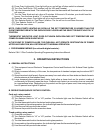
For a stack of two ovens: Refer to Figure 3
(1) Remove flue from bottom oven prior to stacking. When top oven is properly positioned on bottom
oven, re-install the flue back on the bottom oven.
(2) Tilt lower unit over to the left-hand side and position two 6” legs on the right side (one for front and
one for back), secure in place by using 4 bolts (3/8”-16) per leg. Tighten firmly.
(3) Using proper lifting equipment, lift up the left side of the unit and attach the other two legs in the same
way.
(4) Using the lifting equipment, raise the top oven to proper height and slide on top of the bottom oven.
Line up sides and front and fasten to each other at the rear of the units by using a mounting bracket
supplied in the stacking kit.
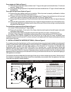
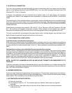
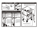
To assemble an open rack stand: Refer to Figure 1
(1) Loosen 12 bolts (attaching 31” legs) slightly.
(2) Remove 4 inner bolts, 1 from each of the 4 legs, place top right angle and top left angle underneath
and tighten these 4 bolts.
(3) Insert “Open Rack Shelf” and tighten into place with eight 3/8-16 screws, washers and nuts.
(4) Position “Rack Supports” and tighten in place using 4 each of flat washers and 5/16-18 Hex Nuts.
Fit the Standard Flue Diverter supplied into the hole in the top of the oven for under ventilation hood
installation and secure with screws. For direct venting, Flue Adapter and Draft Hood must be placed into the
hole on top of the oven.
C. INSTALLATION WITH CASTERS (OPTIONAL): Refer to Figure 4
Four casters (two with wheel brakes) and the mounting hardware are packed and included in the shipment if
ordered. Install casters with wheel brakes on the front of the unit. Installation of the unit should be made with
a connector that complies with the latest edition of the Standard for Connectors for Movable Gas
Appliances ANSI Z21.69 in the USA (CAN CSA-6.16 in Canada) and a quick-disconnect device that
complies with the latest edition of the standard for quick disconnect devices for use with gas fuel ANSI
Z21.41 in the USA (CSA 6.9 in Canada). Adequate means must be provided to limit the movement of the
appliance without depending on the connector and any quick disconnect device or its associated piping to
limit appliance movement.
The restraint should be attached to the rear legs of the oven on which casters are mounted. If disconnect of
the restraint is necessary, the restraint should be immediately reconnected after the appliance has been
returned to its originally installed position.
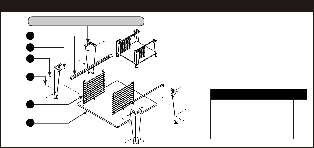
Figure 1
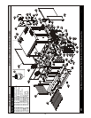
OPEN RACK STAND ASSEMBLY INSTRUCTIONS: BCO-G & GDCO-G
Assembly Instruction
1. Place undershelf (6) between legs & secure
with 1/4-20 UNC screws (4), flat washers (3) &
locknuts (2). The holes for mounting the wire
racks should be toward the front of the oven.
2. Place open rack supports (1) between legs &
secure with 1/4-20 UNC screws (4), flat
washers (3) & locknuts (2).
3. Slide wire rack supports (5) into position using
the holes in the undershelf (6) as a guide.
1
2
3
4
5
6
Open Style Support Leg Not Supplied With Kit
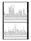
1 21818222 Support, Open Rack 2
2 770504 Lock Nut 1/4-20 12
3 8519600 Washer, Flat 1/4” 12
4 8208200 Screw, 1/4-20 x 3/4” 12
5 21816807 Support, Wire Rack 2
6 21818231 Undershelf, Gas Oven 1
Item P/N Description Quan