


3
observe the clearances detailed in Section D (Location). Provide adequate ventilation and make up air in
accordance with local codes. Servicing your oven is done through the front control panel and right side
access cover. Assure that these areas are kept unobstructed for easy access.
For a single unit:
(1) Tilt Oven over onto left hand side, and attach two 30" legs on the right hand side with three 1/2" bolts
and washers. Tighten firmly.
(2) Using proper lifting equipment lift up the Ieft hand side and attach two 30" legs on the left hand side
the same way.
For a stack of two ovens:
(1) Tilt lower unit over onto the left hand side, attach two mounting plates to the right hand underside
and screw 6" legs into the center holes.
(2) Using proper lifting equipment lift up the left hand side and attach the mounting plates and 6" legs as
in (Step1 ).
(3) Using the lifting equipment, raise the top oven to proper height and slide on top of the bottom oven.
Line up sides and front of both ovens and fasten to each other with stacking brackets.
All legs for the CO11-G 1 and CO11-G2 as well as the base cabinet have a leveling adjustment. Start with
adjustment screwed all the way in. With a spirit Ievel placed on an oven rack, check and level side to side
first and then front to back.
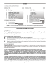
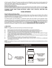
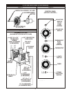
Fit the Standard Flue Diverter supplied (Figure 1) into the hole in the top of the oven (for under ventilation
hood installation) and secure with screws. For direct venting. The Flue Adapter and the Draft Hood must be
placed into the hole on top of the oven(Figure 2).
To assemble an open rack stand: Refer to fig.3
(1) Loosen 12 bolts( attaching 30" legs) slightly.
(2) Remove 4 inner bolts, 1 from each of the four legs. Place top right angle and top left angle
underneath and tighten these 4 bolts.
(3) Insert Open Rack Shelf and tighten into place with eight 3/8-16 screws, washers and nuts.
(4) Position 'Rack Supports' and tighten in place using 4 each of Flat washers and 5/16-18 Hex Nuts.
To assemble over a Base Cabinet:
(1 ) Tilt cabinet over onto the left hand side. Attach two mounting plates to the right underside and screw
6" legs into the center holes.
(2) Lift up left hand side of the base cabinet and attach the mounting plates and 6" Iegs on the
underside and screw 6" legs into center holes.
(3) Using the lifting equipment, raise the top oven to proper height and slide on top of the base cabinet.
Line up sides and front and fasten to each other with stacking brackets.
C. INSTALLATION WITH CASTERS (OPTIONAL):
Four casters (two with wheel brakes) and the mounting hardware are packed and included in the shipment
if ordered.
Install casters with wheel brakes on the front of the unit.
Installation of the unit should be made with a connector that complies with the latest edition of the Standard
for Connectors for Movable Gas Appliances ANSI Z21.69, in the USA (CAN CGA-6.16 in Canada) and a
quick disconnect device that complies with the latest edition of the standard for quick disconnect devices
for use with gas fuel ANSI Z21A I in the USA (CAN 1-6.7 in Canada.) Adequate means must be provided to
limit the movement of the appliance without depending on the connector and any quick disconnect device
or its associated piping to limit the appliance movement.
The restraint should be attached to the rear legs of the oven on which casters are mounted. If disconnection
of the restraint is necessary, the restraint should be reconnected after the appliance has been returned to
its originally installed position.
D. LOCATION AND MINIMUM CLEARANCES:
Move the oven to its final location keeping the minimum clearance from the back of the oven to the wall.
This clearance is necessary for safe operation and to provide proper air flow to the burner chamber.