


installation and thence to an independent earth connection in compliance with EN 60335-1 and/or local
codes.
The electric motor, all the related switches, interior lights and the timer/buzzer, are all connected through
the 6ft (1829 mm) power supply cord located at the rear of the oven. The supply cord must be plugged into a
properly grounded three-prong receptacle. DO NOT CUT OR REMOVE THE GROUNDING PRONG
FROM THE PLUG.
Normal factory connections are made for 115 volts AC., 60 Hz. Service in USA and Canada or 230Volts AC,
50 Hz service in European Community Countries. Other voltages can be supplied upon request. Electrical
characteristics of this unit can be found on the rating plate located on the right side of the unit.
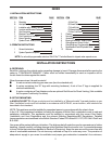
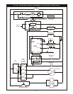
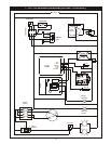
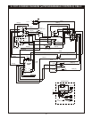
This unit is provided with a permanently lubricated electric motor. A wiring diagram may be found on the
back of the service panel on the right hand side and in this manual.
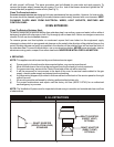
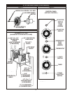
G. FLUE CONNECTION - VENTILATION:
(a) INSTALLATION UNDER VENTILATION HOOD (STANDARD):
If the oven is not vented directly and is installed under a ventilation hood, use the flue diverter (Fig. 1)
supplied. Local inspectors and ventilation specialist should be consulted so that the design and the
installation of the hood conforms to local/municipal codes.
In U.K. ventilation requirements as detailed in B.S. 5440 should be followed.
(b) OPTIONAL DIRECT VENTING-NOT AVAILABLE FOR EUROPEAN COMMUNITY COUNTRIES:
If direct venting, a flue adapter and a draft hood (fig.2) are required to be installed. These prevent the flue
gases leaving the oven from being affected by the air pressure changes on the outside of the flue stack
extending out of the building. The flue pipe from the draft hood must not run downwards at any point from
the oven to the final outlet. It should always slant slightly upwards. For best results it should rise straight up
NOTE: DO NOT PUT A DAMPER IN THE FLUE AND DO NOT CONNECT A BLOWER DIRECTLY TO
THE FLUE.
If the flue runs directly to the free air outside the building, use a wind deflector or a UL listed vent cap at the
end of the pipe. Termination of the vent must be at least two feet above the highest part of the roof within ten
feet. REF: AGA CATALOG NO. XH0474.
H. BURNER OPERATION:
The oven burner flame should always have a blue appearance. This indicates a good mixture of air and gas.
When using LP gas the flame will have a blue yellow appearance. There may be intermittent yellow-orange
flame noticed. This is caused by dust particles burning in the flame.
I. SYSTEM CHECK - ROTARY CONTROL:
I) Open the oven door.
2) Turn Selector Switch to 'Hi'. The indicator light near Selector Switch and oven light will illuminate.
3) Close the door. Oven lights will go off and fan will run. Make sure fan is rotating clockwise looking
from front.
4) Press Oven Light switch. Oven light will go on and will go off as switch is released.
5) Turn Gas Cock Dial to 'ON' position.(only for USA & Canada)
6) Turn the thermostat knob. The indicator light near the thermostat will Illuminate and the burners will
come on.
7) Turn the Timer Knob and set a time of 2 minutes. At the end of 2 minutes, you should hear the
buzzer. Turn the timer knob to '0' to reset.
8) Open the oven doors. Oven lights will go on, and burners and fan will go off.
9) Turn Selector switch to 'Cool Down' position. The fan will run to cool down the oven.
10) Turn Selector Switch to '0' position.
5