


TABLE OF CONTENTS
1 Receiving 5
2 Location & Minimum Clearances 5
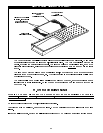
3 Installation 5
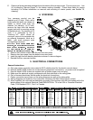
4 Stacking 6
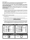
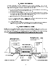
5 Electrical Connections 6
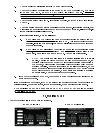
6 System Check 8
7 Initial Start-Up 10
8 Shutdown 11
9 Special Features 11
10 Cleaning 12
11 Operator Maintenance 13
12 Rating Plate 14
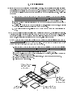
13 Conveyor Removal 15
14 Conveyor Installation 15
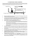
15 Conveyor Belt Speed Calibration 16
16 Troubleshooting Guide 18
17 Temperature Control Conversion Chart 23
18 Solid State Relay Identification 24
19 Electrical Schematics & Wiring Diagrams 26
A.
B.
C. 3
VHVA1620E Schematic, 208, 220 or 240VAC, 1 Phase 26
VHVA 1620E Wiring Diagram, 208, 220 or 240VAC, 1 Phase 27
VHVA1620E Schematic, 208, 220 or 240VAC, Phase 28
D. VHVA 1620E Wiring Diagram, 208, 220 or 240VAC, 3 Phase 29
E. VH 1620E Schematic, 208, 220 or 240VAC, 1 Phase 30
F. VH 1620E Wiring Diagram, 208, 220 or 240VAC, 1 Phase 31
G. VH 1620E Schematic, 208, 220 or 240VAC, 3 Phase 32
H. VH 1620E Wiring Diagram, 208, 220 or 240VAC, 3 Phase 33
I. VHVA 1828E Schematic, 208, 220, or 240, 1 Phase 34
J. VHVA 1828E Wiring Diagram, 208, 220, or 240, 1 Phase 35
K. VHVA 1828E Schematic, 208, 220, or 240, 3 Phase 36
L. VHVA 1828E Wiring Diagram, 208, 220, or 240, 3 Phase 37
M. VH 1828E Schematic, 208, 220, or 240, 1 Phase 38
N. VH 1828E Wiring Diagram, 208, 220, or 240, 1 Phase 39
O. VH 1828E Schematic, 208, 220, or 240, 3 Phase 40
P. VH 1828E Wiring Diagram, 208, 220, or 240, 3 Phase 41
20 Parts Lists & Exploded Views 42
A. External Covers 42
B. Conveyor Assembly 42
C. Blower Motor Cover Assembly 43
D. Blower Assembly 43
E. VH Series Only 43
F. Plenum “Finger” Assembly 43
G. Main Power Control Box 44
H. Electric Control Box 45
I. Cool Down Thermostat, Elements, Switch & Probe 46
21 Warranty 47