


ENGLISH
XENYX 1622FX/1832FX/2222FX/2442FX User Manual
6
ENGLISH
XENYX 1622FX/1832FX/2222FX/2442FX User Manual
7
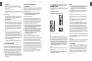
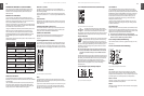
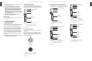
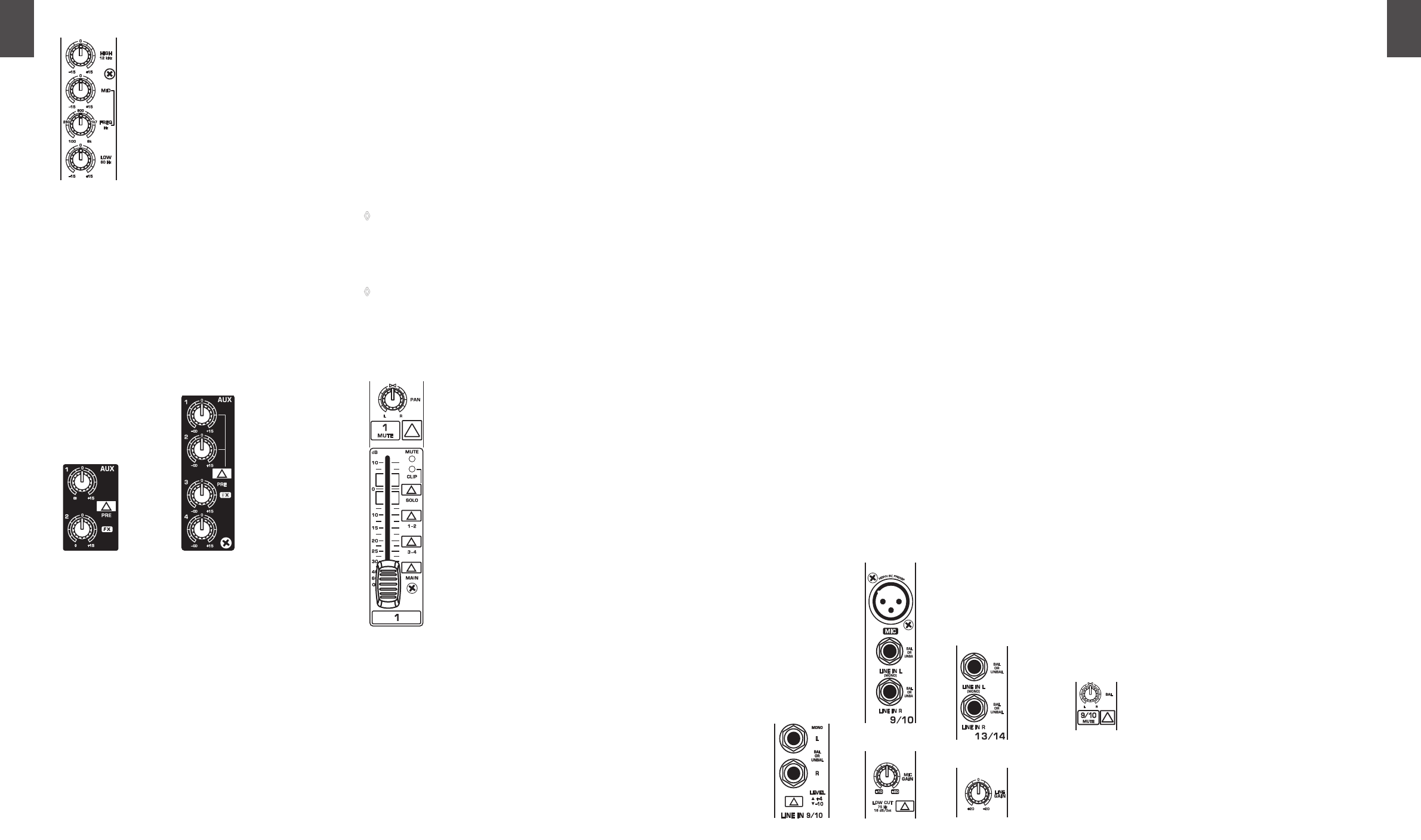
Fig. 2.2: Equalizer of the input channels
The upper (HIGH) and the lower (LOW) bands are shelving
lters that increase or decrease all frequencies above or
below their cut-o frequency. The cut-o frequencies
of the upper and lower bands are 12 kHz and 80 Hz
respectively. For the mid range, the console features a
semi-parametric equalizer with a lter quality (Q) of 1
octave, tunable from 100 Hz to 8 kHz. Use the MID control
to set the amount of boost or cut, and the FREQ control to
determine the central frequency.
Monitor and eects busses (Aux sends)2.1.3
Fig. 2.3: Aux Send control MON and FX in the channel strips
Monitor and eects busses (AUX sends) source their signals via
a control from one or more channels and sum these signals to
a so-called bus. This bus signal is sent to an aux send connector
(for monitoring applications: MON OUT) and then routed,
for example, to an active monitor speaker or external eects
device. In the latter case, the eects return can then be brought
back into the console via the aux return connectors.
All monitor and eects busses are mono, are tapped into
post EQ and oer amplication of up to +15 dB.
Pre-fader/post-fader
When using eects on a channel signal, it is usual to have
the aux send post fader so that the balance between eect
and dry signal stays constant even when the channel fader
is altered. If this were not the case, the eects signal of the
channel would remain audible even when the channel fader
is turned all the way down. For monitoring, the aux sends are
generally pre-fader, i.e. they operate independently of the
position of the channel fader.
PRE
When the PRE switch is pressed down, the associated aux
send is taken pre-fader.
FX
The aux send marked FX oers a direct route to the built-in
eects processor and is therefore post-fader and post-mute.
Please refer to chapter 4 “DIGITAL EFFECTS PROCESSOR” for
detailed information.
If you are using the built-in eects processor, make ◊
sure that STEREO AUX RETURN 3 has nothing plugged
into it (2442FX and 2222FX), otherwise the internal
eects return will be muted. This is not relevant if you
use the FX OUT jack to drive an external eects device.
1622FX and 1832FX: On these consoles, the above ◊
note refers to the STEREO AUX RETURN 2 jacks as these
models do not have a dedicated eect output.
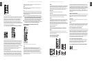
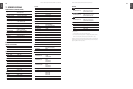
Routing switch, PAN, SOLO and 2.1.4
channel fader
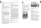
Fig. 2.4: The panorama and routing controls and the channel fader
PAN
The PAN control determines the position of the channel
signal within the stereo image. When working with
subgroups, you can use the PAN control to assign the signal
to just one output, which gives you additional exibility
in recording situations. For example, when routing to
subgroups 3 and 4, panning hard left will route the signal
to group output 3 only, and panning hard right will route to
group output 4 only.
All Models
XENYX1622FX XENYX2442FX
XENYX2442FX
MUTE
The MUTE switch breaks the signal path pre-channel fader,
hence muting that channel in the main mix. The aux sends
which are set to post-fader are likewise muted for that
channel, while the pre-fader monitor paths remain active
irrespective of whether the channel is muted or not.
MUTE LED
The MUTE LED indicates a muted channel.
CLIP-LED
The CLIP-LED lights up when the input signal is driven
too high. If this happens, back o the GAIN control and, if
necessary, check the setting of the channel EQ.
SOLO
The SOLO switch is used to route the channel signal to the
solo bus (Solo In Place) or to the PFL bus (Pre Fader Listen).
This enables you to listen to a channel signal without
aecting the main output signal. The signal you hear is
taken either before the pan control (PFL, mono) or after the
pan and channel fader (Solo, stereo) (cf. chap. 2.3.10 “Level
meters and monitoring”).
SUB (1-2 and 3-4)
The SUB switch routes the signal to the corresponding
subgroups. The 2442FX has 4 subgroups (1-2 and 3-4).
MAIN
The MAIN switch routes the signal to the main mix bus.
The channel fader determines the channel’s volume in the
main mix (or submix).
Stereo channels2.2
Channel inputs2.2.1
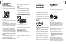
Fig. 2.5: The various stereo channel inputs
Each stereo channel has two balanced line level inputs on
jacks for left and right channels. Channels 9/10 and 11/12 on
the 2442FX feature an additional XLR microphone jack with
phantom power. If only the left jack (marked “L”) is used, the
channel operates in mono. The stereo channels are designed
to handle typical line level signals, and, depending on
model, have a level switch (+4 dBu or -10 dBV) and/or a line
GAIN control. Both jack inputs will also accept unbalanced
connectors.
LOW CUT and MIC GAIN
These two control elements operate on the XLR connectors
of the 2442FX, and are used to lter out frequencies below
75 Hz (LOW CUT) and to adjust microphone levels (MIC
GAIN).
LINE GAIN
Use this control to adjust the line signal levels on channels
13-16 (2442FX only).
LEVEL
For level matching, the stereo inputs on the 1622FX, 1832FX
and 2222FX have a LEVEL switch to select between +4 dBu
and -10 dBV. At -10 dBV (homerecording level), the input is
more sensitive than at +4 dBu (studio level).
Equalizer stereo channels2.2.2
The stereo channels contain a stereo EQ section. The cut-o
frequencies of the high and low bands are 12 kHz and 80 Hz
respectively, while the center frequencies of the high-mid
and low-mid bands are 3 kHz and 500 Hz respectively. The
HIGH and LOW controls have the same characteristics as the
EQ in the mono channels. Both mid range bands are of the
peak lter type. A stereo EQ is superior to two mono EQs on
a stereo signal as two separate EQs will usually result in a
discrepancy between left and right channels.
Aux sends stereo channels2.2.3
In principle, the aux sends of the stereo channels function
the same way as those of the mono channels. As the aux
sends are mono, the send from a stereo channel is rst
summed to mono before it reaches the aux bus.
Routing switch, solo and channel fader2.2.4
Fig. 2.6: Balance control and mute switch
XENYX2222FX XENYX2442FXXENYX2442FX