


ENGLISH
XENYX 1622FX/1832FX/2222FX/2442FX User Manual
14
ENGLISH
XENYX 1622FX/1832FX/2222FX/2442FX User Manual
15
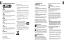
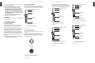
DIGITAL EFFECTS 4.
PROCESSOR
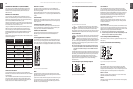
24-BIT MULTI-EFFECTS PROCESSOR
Here you can nd a list of all presets stored in the multi-
eects processor. This built-in eects module produces
high-grade standard eects such as reverb, chorus, anger,
delay and various combination eects. Use the Aux Send
FX on the channels and the Aux Send FX master control to
determine the input signal of the eects processor.
Fig. 4.1: Digital eects module
The built-in stereo eects processor has the advantage that
it does not need to be wired up. This excludes the danger
of humming or level mismatch right from the start and thus
considerably facilitates use.
These eect presets are classical “mixing eects”. If you move
the STEREO AUX RETURN FX control, you mix the channel
signal (dry) and the eect signal. You can control the balance
between the two signals with the channel fader and the
STEREO AUX RETURN FX control.
FX OUT
Mixing consoles 2222FX and 2442FX have a separate output
for the eects device, which is unbalanced and stereo (tip
= left signal; ring = right signal; sleeve = ground/shielding).
Thus, you can record, for example, a vocal track enhanced
with reverb in parallel to a “dry” vocal track; when doing the
mix-down later on, you can freely determine the amount of
reverb added.
The 2442FX has the eect output on the rear, 2222FX ◊
has it located next to the aux sends on the front panel.
FX FOOTSW.
Connect a standard foot switch to the foot switch jack and
use this to switch the eects processor on and o. A light
at the bottom of the display indicates wheater the eects
processor has been muted by the foot switch.
In Chapter 6.2 you will nd an illustration showing how ◊
to connect your foot switch correctly.
LEVEL
The LED level meter on the eects module should display
a suciently high level. Take care to ensure that the clip
LED only lights up at peak levels. If it is lit constantly, you
are overloading the eects processor and this could cause
unpleasant distortion.
PROGRAM
You can select the eect preset by turning the PROGRAM
control. The display ashes with the number of the current
preset. To recall the selected preset, press on the button; the
ashing stops. You can also recall the selected preset with
the foot switch.
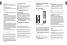
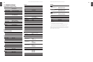
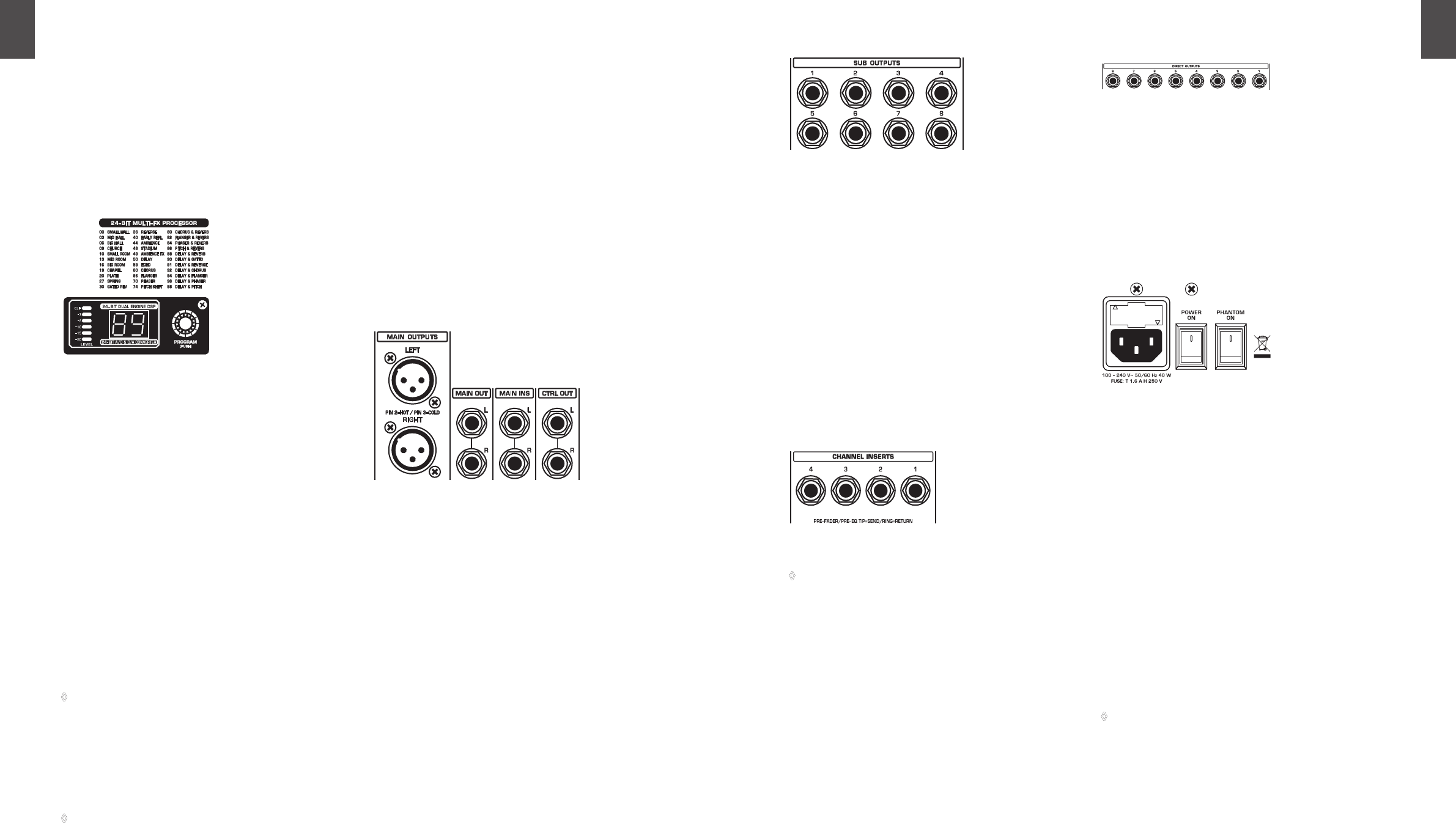
REAR PANEL CONNECTORS5.
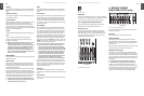
Main mix outputs, insert points and 5.1
control room outputs
Fig. 5.1: Main Mix outputs, main mix insert points and control room outputs
MAIN OUTPUTS
The MAIN outputs carry the MAIN MIX signal and are on
balanced XLR jacks with a nominal level of +4 dBu. In parallel
with this, ¼" phone jacks carry the main mix signal in a
balanced format (1622FX: here, the phone jack outputs are
unbalanced and located on the front panel).
CONTROL ROOM OUTPUTS (CTRL OUT)
The control room output is normally connected to the
monitoring system in the control room and carries the stereo
mix or, when selected, the solo signals.
MAIN INS(ERTS) (2442FX only)
These are the insert points for the main mix. In the signal
path, they are post-main mix amp, but pre-main fader(s). Use
them to insert, for example, a dynamics processor or graphic
equalizer. Please also note the information on insert points in
chapter 5.3.
XENYX1832FX
XENYX2442FX
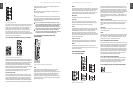
Subgroup outputs5.2
Fig. 5.2: Subgroup outputs
SUB OUTPUTS
The subgroup outputs are unbalanced and provide the mix
of those channels assigned to each subgroup with the SUB
switch (2442FX: switches 1-2 or 3-4) next to the channel
faders. Thus, you can, for example, route a subgroup to a
second console or use the output as a recording output
in parallel to the main outputs. In this way, you can record
several tracks simultaneously. With an 8-track recorder, use Y
cables and wire the inputs of your machine so that you have 2
x 4 tracks available (e.g. channel 1 to track 1 and 2, etc.). In the
rst pass, you can record the tracks 1, 3, 5 and 7, in the second
the tracks 2, 4, 6 and 8.
The XENYX 2442FX already has subgroup outputs wired in
parallel (1-5, 2-6, etc.).
Inserts5.3
Fig. 5.3: Insert points
On the 2442FX the channel insert points are located ◊
on the control panel between the line input and the
GAIN control.
Insert points are very useful to process channel signals
with dynamic processors or equalizers. Unlike reverb or
other eects devices, whose signals are usually added
to the dry signal, dynamic processors are most eective
on the complete signal. In this case, aux send paths are a
less-than-perfect solution. It is better to interrupt the signal
path and insert a dynamic processor and/or equalizer.
After processing, the signal is routed back to the console
at precisely the same point it left. However, the channel
signal path is interrupted only if a plug is inserted into the
corresponding jack (stereo phone plug: tip = signal output;
ring = return input). All mono input channels are equipped
with inserts. They are pre-fader, pre-EQ and pre-aux send.
Inserts can also be used as pre-EQ direct outputs, without
interrupting the signal path. To this end, you will need a
cable tted with mono phone plugs on the tape machine or
eect device end, and a bridged stereo phone plug on the
console side (tip and ring connected).
Direct outputs (2442FX only)5.4
Fig. 5.4: Direct outputs
DIRECT OUTPUTS
The direct outputs of the 2442FX (1 each per mono input
channel) are ideal for recording if several tracks are to be
recorded simultaneously. These unbalanced phone jacks are
post-EQ, post-mute and post-fader.
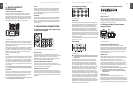
Voltage supply, phantom power 5.5
supply and fuse
Fig. 5.5: Voltage supply and fuse
FUSE HOLDER/IEC MAINS RECEPTACLE
The console is connected to the mains via the cable
supplied, which meets the required safety standards. Blown
fuses must only be replaced by fuses of the same type and
rating. The mains connection is made via a cable with IEC
mains connector. An appropriate mains cable is supplied
with the equipment.
POWER switch
Use the POWER switch to turn on the mixing console. The
POWER switch should always be in the “O” position when
you are about to connect your unit to the mains.
To disconnect the unit from the mains, pull out the main
cord plug. When installing the product, ensure that the plug
is easily accessible. If mounting in a rack, ensure that the
mains can be easily disconnected by a plug pull or by an all-
pole disconnect switch on or near the rack.
Attention: The POWER switch does not fully disconnect ◊
the unit from the mains. Unplug the power cord
completely when the unit is not used for prolonged
periods of time.
PHANTOM switch
The PHANTOM switch activates the phantom power
(necessary to operate condenser microphones) on the XLR
sockets of the mono channels. The red +48 V LED illuminates
when phantom power is on. As a rule, dynamic microphones
can still be used with phantom power, provided that they are
XENYX1622FX
XENYX2442FX
All Models