


ENGLISH
XENYX 1622FX/1832FX/2222FX/2442FX User Manual
10
ENGLISH
XENYX 1622FX/1832FX/2222FX/2442FX User Manual
11
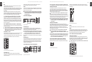
STEREO AUX RETURN 1/2 (TO AUX SEND)
The two right-hand STEREO AUX RETURN controls have a
special function: they can be used to add an eect to a
monitor mix. An example follows (1622FX wired to an
eects device):
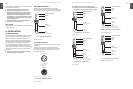
Monitor mix with eect
In this instance, your eects device should be set up as
follows: the AUX SEND 2 jack should be connected to the L/
Mono input of your eects device, with its outputs coming
back into the STEREO AUX RETURN 1 jacks.
Connect the AUX SEND 1 jack output to the amplier of your
monitor system. The AUX SEND 1 master control determines
the overall volume of the monitor mix.
Using the STEREO AUX RETURN (TO AUX SEND) control, the
eect signal can now be blended into the monitor mix.
You can easily use the headphones distribution amplier
BEHRINGER POWERPLAY PRO HA4700/HA8000 to provide
four (HA8000: eight) stereo headphone mixes for your
studio.
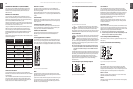
The following table shows which jacks on the console can be
used for this purpose.
External eects device
receives signal from
...
External eects device
routes signal back to
...
The eect signal reaches
the monitor mix via
…
1622FX
AUX SEND 2
STEREO AUX
RETURN 1 connectors
STEREO AUX
RETURN 1 (TO AUX SEND
1) control
1832FX
AUX SEND 1
STEREO AUX
RETURN 2 connectors
MONITOR switch of the FX/
AUX 2 RET
2222FX
AUX SEND 2
STEREO AUX
RETURN connectors
1 or 2
STEREO AUX
RETURN 1 (TO AUX SEND
1) control
2442FX
AUX SEND 2
STEREO AUX
RETURN 1 connectors
STEREO AUX
RETURN 1 (TO AUX SEND
1) control
optional:
AUX SEND 1
STEREO AUX
RETURN 2 connectors
STEREO AUX
RETURN 2 (TO AUX SEND
2) control
Tab. 2.1: Connectors and controls for monitor mix with eect
STEREO AUX RETURN FX
On consoles 1622FX and 1832FX this is the STEREO AUX
RETURN 2, on consoles 2222FX and 2442FX this is the STEREO
AUX RETURN 3.
Use the STEREO AUX RETURN FX control to determine the
level of the signal routed from the AUX RETURN FX jacks
to the main mix. If nothing is connected to these jacks, the
output of the built-in eects module will appear.
MAIN MIX / TO SUBS
This switch routes the signal fed in via the STEREO AUX
RETURN FX jacks either to the main mix (not pressed) or to
the submix (pressed).
On the 2442FX you can select which subgroup the signal is
assigned to (switches 1-2 / 3-4, to the right of MAIN MIX / TO
SUBS).
SOLO RETURNS
Additionally, this model allows you to route the aux returns
together to the solo bus and the PFL bus. The LED lights up
when Solo is on.
STEREO AUX RETURN 4 (2442FX only)
This control behaves the same way as the other stereo aux
returns. Additionally, it provides for a simple monitor path
using the switch PHONES/CTRL ROOM ONLY.
PHONES/CTRL ROOM ONLY
Use this switch to route the signal appearing at the AUX
RETURN 4 jacks to the control room and headphones
outputs.
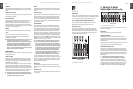
Supplement to 1832FX2.3.6
The 1832FX has a stereo fader for the AUX RETURN FX and
oers a variety of routing options: MUTE disables the eect
return (but not PFL of course!), SOLO routes it to the Solo or
PFL busses, SUB to the subgroups and MAIN to the main mix.
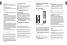
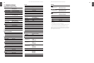
Fig. 2.13: The FX/AUX 2 return fader of the 1832FX
MON
The MON switch routes the signals appearing at the AUX
RETURN 2 jacks to the monitor path, along with the monitor
signals from the channels.
If you wish to route the eect signal to the monitor mix, you
can also switch aux 1 to pre-fader, drive the eect device
from the aux 1 output and return the eect signal via AUX
RETURN 2 to the monitor signal.
XENYX1832FX
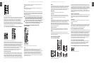
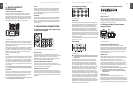
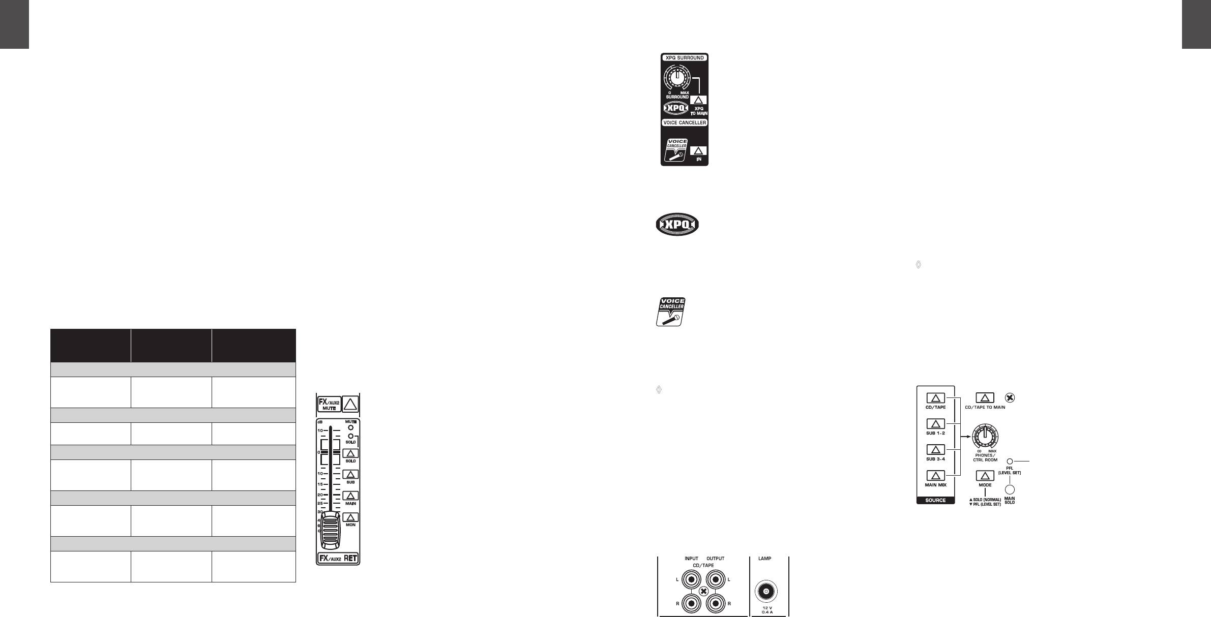
XPQ Surround function (1832FX only)2.3.7
Fig. 2.14: Control elements of the surround function
The XPQ surround function can be enabled/
disabled with the XPQ TO MAIN switch. This is a
built-in eect that widens the stereo width,
thus making the sound more lively and trans-parent. Use the
SURROUND control to determine the intensity of this eect.
VOICE CANCELLER
Here, you have a lter circuitry that lets you almost
entirely remove the vocal portion of a recording.
The lter is constructed in such a way that voice
frequencies are targeted without majorly aecting
the rest of the signal. Additionally, the lter seizes only the
middle of the stereo image, exactly there where the vocals
are typically located.
Connect the signal sources you wish to process using ◊
the Voice Canceller to the CD/TAPE INPUT connectors.
The Voice Canceller circuitry is not available for other
inputs.
Possible applications for the Voice Canceller are obvious: you
can very simply stage background music for Karaoke events.
Of course, you can also do this at home or at your rehearsal
room before you hit the stage. Singers with their own
band can practice singing dicult parts using a complete
playback from a tape player or a CD, thus minimizing
rehearsal time.
CD/Tape input, CD/tape output2.3.8
Fig. 2.15: 2-track connectors and lamp socket
CD/TAPE INPUT
The CD/TAPE INPUT jacks (RCA) are designed to accept a
2-track recorder (e.g. DAT recorder), or they can be used as
stereo line input. The output signal of a second XENYX or the
BEHRINGER ULTRALINK PRO MX882 can also be connected
here. If you connect the output of a hi- amplier (with a
source selection switch) to the CD/TAPE INPUT, you can
easily listen to additional sources (e.g. cassette recorder,
MD player, sound card, etc.).
Using the voice canceller function (1832FX only), you can
process all signals being brought into your mixing console
via these connectors.
CD/TAPE OUTPUT
These connectors are wired in parallel to the MAIN OUT and
carry the main mix signal (unbalanced). Connect this to the
inputs of your recording device. The nal output level can be
adjusted via the high-precision MAIN MIX fader.
If you connect a compressor or a noise gate post ◊
2-track output, the main mix fader will probably not be
able to create a satisfactory fade-out eect.
Lamp socket (2442FX only)2.3.9
Use this BNC socket to connect a gooseneck lamp (12 V DC,
max. 0.5 A).
Level meter and monitoring2.3.10
Fig. 2.16: Control room and phones sections of the 2442FX
CD/TAPE
The CD/TAPE switch routes the signal from the CD/TAPE
INPUT jacks to the level meter, the CONTROL ROOM OUT
outputs and the PHONES jack—this is a simple way to check
recorded signals via monitor speakers or headphones.
SUB 1-2 or SUB
The SUB 1-2 switch routes subgroup 1-2 to the level meter,
CONTROL ROOM OUT and phones.
SUB 3-4
The SUB 3-4 switch performs a similar function for subgroup
3-4 (2442FX only).
XENYX1832FX
XENYX1832FX
XENYX2442FX