


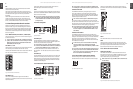
ENGLISH
XENYX 1622FX/1832FX/2222FX/2442FX User Manual
12
ENGLISH
XENYX 1622FX/1832FX/2222FX/2442FX User Manual
13
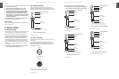
MAIN MIX
The MAIN MIX switch sends the main mix to the CONTROL
ROOM OUT and the PHONES output as well as to the level
meter.
PHONES/CTRL ROOM
Use this control to adjust the control room output level and
the headphones volume.
CD/TAPE TO MAIN
When the CD/TAPE TO MAIN switch is depressed, the 2-track
input is routed to the main mix and thus serves as an
additional input for tape machines. You can also connect
MIDI instruments or other signals here that do not require
any further processing. At the same time, this switch disables
the main mix to tape output link.
POWER
The blue POWER LED indicates that the device is switched on.
+48 V
The red “+48 V” LED lights up when phantom power
is switched on. Phantom power is required to operate
condenser microphones.
While phantom power is switched on, do not connect ◊
or disconnect microphones on the mixer (or the
stagebox/wallbox). Connect any micro-phones before
switching on phantom power. Additionally, monitor/
PA speakers should be muted before you activate
the phantom power supply. After switching on, wait
approx. one minute before adjusting the input gain so
that the system has time to stabilize.
LEVEL METER
The high-precision level meters always give you an accurate
display of signal level.
LEVEL SETTING:
When recording to digital recorders, the recorder’s meter
should not go into overload. This is because, unlike analog
recordings, it takes only slightly excessive levels to create
unpleasant digital distortion.
When recording to analog, the VU meters of the recording
machine should reach approx. +3 dB with low-frequency
signals (e.g. kick drum). Due to their inertia, VU meters tend
to display too low a signal level at frequencies above 1 kHz.
You should only drive instruments such as a Hi-Hat as far as
-10 dB. Snare drums should be driven to approx. 0 dB.
The peak meters of your XENYX display level almost ◊
independent of frequency. A recording level of 0 dB is
recommended for all types of signal.
MODE
The MODE switch determines whether the channels’ SOLO
switch operates as PFL (Pre Fader Listen) or as solo (Solo In
Place).
PFL (LEVEL SET)
To activate the PFL function, press the MODE switch. The PFL
function should, as a rule, be used for level setting (GAIN).
The signal is sourced pre-fader and assigned to the mono
PFL bus. In “PFL” mode, only the left side of the peak meter
is in operation. A PFL’d channel should be driven to the 0 dB
mark of the VU meter.
SOLO (NORMAL)
When the MODE switch is not depressed, the stereo solo
bus is active. Solo is actually short for “Solo In Place”. This is
the customary method for listening to an individual signal
or to a group of signals. As soon as a solo switch is pressed,
all channels not solo selected are muted in th e monitor
path (control room and phones). A channel’s position in the
stereo image is maintained. The solo bus carries the output
signals of the channel pan controls, the aux sends and the
stereo line inputs. On the 2442FX all aux returns, and on the
1832FX only aux return 2 can be routed to the solo bus. The
solo bus is, as a rule, taken post-fader.
The PAN control in the channel strip oers a constant ◊
power characteristic. This means that the signal is
always at a constant level, irrespective of position in
the stereo panorama. If the PAN control is moved fully
left or right, the level in that channel increases by 4 dB.
This ensures that, when set at the center of the stereo
image, the audio signal does not appear louder. For
this reason, with the solo function activated (Solo in
Place), audio signals from channels with PAN controls
that have not been moved fully left or right are
displayed at a lower volume than in the PFL function.
As a rule, solo signals are monitored via the control room
outputs and headphones jack and are displayed by the level
meters. If a solo switch is pressed, the signals from the tape
input, the subgroups and the main mix are cut from these
outputs and the level meter.
MAIN SOLO
The MAIN SOLO LED lights up as soon as a channel or aux
send solo switch is pressed. The MODE switch must be set to
“Solo”.
PFL (LEVEL SET)
The PFL (LEVEL SET) LED indicates that the peak meter is set
to PFL mode.
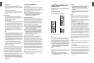
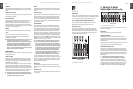
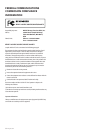
Fig. 2.17: PHONES jack
PHONES jack
You can connect headphones to this ¼" stereo jack (2442FX:
2 phones jacks). The signal routed to the PHONES connection
is the same as that routed to the control room output.
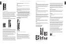
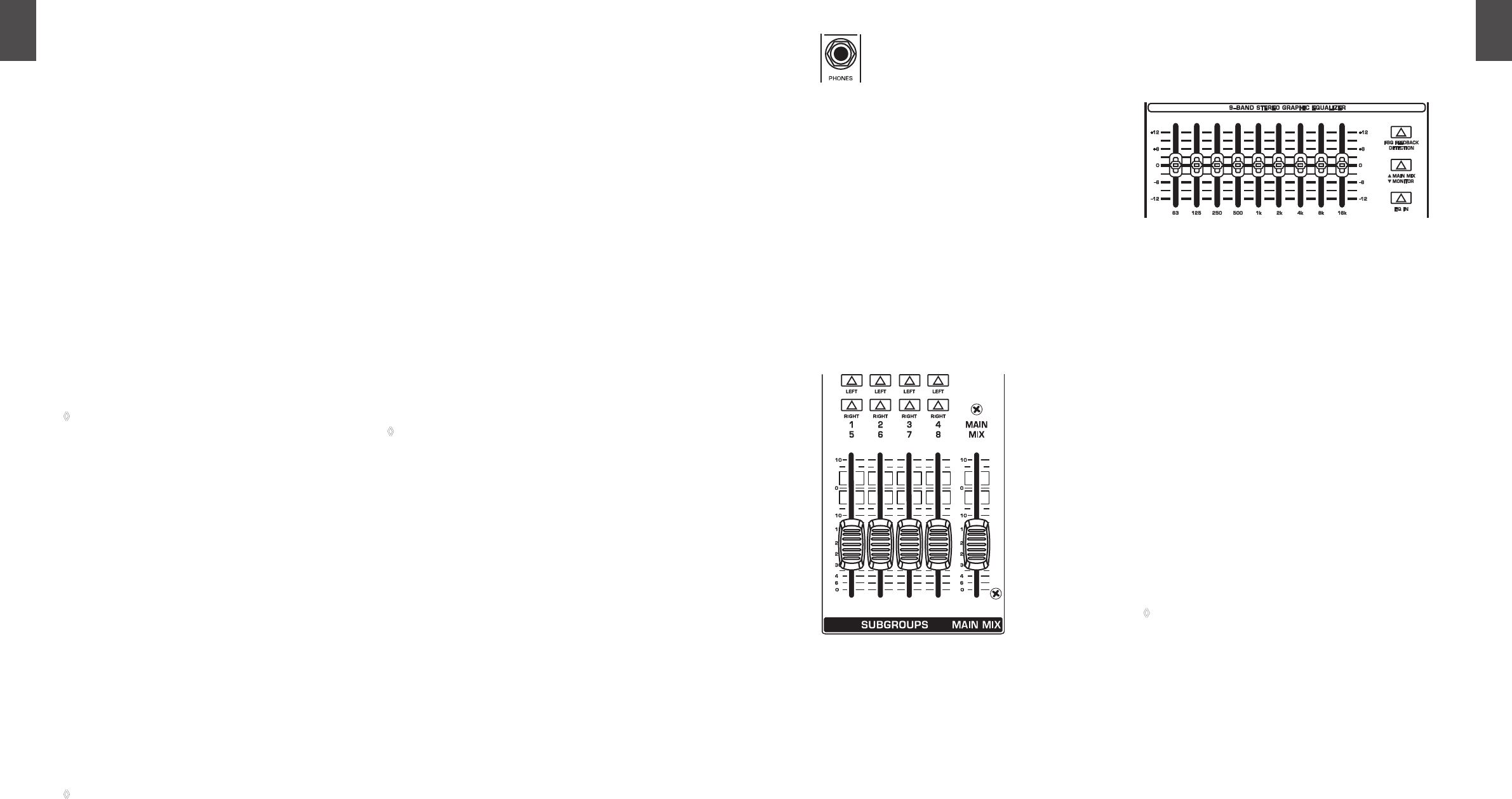
Subgroups and main mix fader2.3.11
You use the high-precision quality faders to control the
output level of the subgroups and the main mix.
LEFT/RIGHT switch
The switches located above the subgroup faders assign
the subgroup signal either to the left or right side of the
main bus. Similarly, it can be routed to both sides or none
at all. In the latter case, the submix is present only at the
corresponding subgroup outputs.
Fig. 2.18: Subgroup and main mix faders
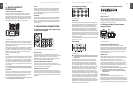
GRAPHIC 9-BAND 3.
EQUALIZER (1832FX only)
Fig. 3.1: The graphic stereo equalizer of the 1832FX
The graphic stereo equalizer allows you to tailor the sound
to the room acoustics.
EQUALIZER
Use this switch to activate the graphic equalizer.
MAIN MIX/MONITOR
This toggles the graphic equalizer between the main mix
and the monitor mix. With the switch up (not depressed), the
equalizer is active in stereo on the main mix, and inactive on
the monitor mix.
When the switch is depressed the equalizer is active in mono
on the monitor mix, and inactive on the main mix.
FBQ FEEDBACK DETECTION
The switch turns on the FBQ Feedback Detection System. It
uses the LEDs in the frequency band faders to indicate the
critical frequencies. On a per-need basis, lower the frequency
range in question somewhat in order to avoid feedback. The
graphic stereo equalizer has to be turned on in order to use
this function.
Logically, at least one (ideally several) microphone ◊
channels have to be open for feedback to occur at all!
Feedback is particularly common when stage monitors
(“wedges”) are concerned, because monitors project sound
in the direction of microphones. Therefore, you can also use
the FBQ Feedback Detection for monitors by placing the
equalizer in the monitor bus (see MAIN MIX/MONITOR).
XENYX2442FX
XENYX1832FX