


10 EURORACK PRO RX1202FX User Manual
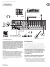
CD/TAPE TO MIX
When the CD/TAPE TO MIX switch is pressed, the CD/tape input is assigned to
the main mix providing an additional input for tape machines, MIDI instruments
or other signal sources that do not require any processing.
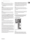
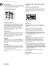
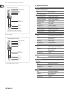
Digital eects processor2.5
Fig. 2.5: Eects section
100 FIRST-CLASS EFFECTS
The EURORACK RX1202FX features a built-in digital stereo eects processor.
This eects processor oers a large number of standard eects such as Hall,
Chorus, Flanger, Delay and various combination eects. Using the FX control,
you can feed signals into the eects processor. The integrated eects
module has the advantage of requiring no wiring. This way, the danger of
creating ground loops or uneven signal levels is eliminated at the outset,
completely simplifying the handling.
SIG and CLIP LED
The SIG LED on the eects module shows the presence of a signal whose level
is high enough. This LED should always be on. However, make sure that the
CLIP LED lights up only sporadically. If it is lit constantly, you are overdriving
the eects processor, which leads to unpleasant distortion. If this occurs,
turn the FX controls down somewhat.
PROGRAM
The PROGRAM control has two functions: by turning the PROGRAM control,
you dial the number of an eect. The number of the preset you just dialed up
blinks in the display. To conrm your selection, press the PROGRAM control;
the blinking stops.
FX TO MAIN
By using the FX TO MAIN controller, the eects signal is sent to the main mix.
No eects signal is to be heard in the summed signal of the mixer when the
controller is positioned entirely to the left. Choose this position if you want to
use an external eects device for the FX output.
An overview of all the multieect processor’s presets are to be found in
the appendix.
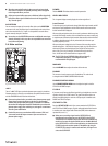
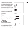
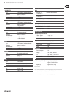
Voltage supply, phantom power supply 2.6
and fuse
FUSE HOLDER/IEC MAINS RECEPTACLE
The mains connection is made via a cable with an IEC mains connector and
meets the required safety standards. An appropriate mains cable is supplied
with the equipment. Blown fuses must only be replaced by fuses of the same
type and rating.
Fig. 2.6: Voltage supply and fuse
POWER switch
Use the POWER switch to turn on the mixing console. The POWER switch
should always be in the “O” position when you are about to connect your unit
to the mains.
To disconnect the unit from the mains, pull out the main cord plug.
When installing the product, ensure that the plug is easily accessible.
If mounting in a rack, ensure that the mains can be easily disconnected
by a plug pull or by an all-pole disconnect switch on or near the rack.
Attention: The POWER switch does not fully disconnect the unit from ◊
the mains. Unplug the power cord completely when the unit is not
used for prolonged periods of time.
PHANTOM switch
The PHANTOM switch activates the phantom power (necessary to operate
condenser microphones) on the XLR sockets of the mono channels.
The red +48 V LED illuminates when phantom power is on. As a rule,
dynamic microphones can still be used with phantom power, provided that
they are wired in a balanced conguration. In case of doubt, contact the
microphone manufacturer!
Connect microphones ◊ before you switch on the phantom power supply.
Please do not connect microphones to the mixer (or the stagebox/
wallbox) while the phantom power supply is switched on. In addition,
the monitor/PA loud-speakers should be muted before you activate the
phantom power supply. After switching on, wait approx. one minute to
allow for system stabilization.
Caution! Please also note the information given in chapter 4.2 ◊
“Audio connections”.
SERIAL NUMBER
Please note the important information on the serial number given in
chapter 1.3.3.