


3
ROOM VENTILATION
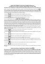
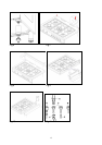
To ensure that the appliance operate correctly, the room where it is installed must be continuously ventilated. The room
volume should not be less than 25 m³ and the quantity of air needed shall be based on the regular combustion of gas
and on the ventilation of the room. Natural air will flow through permanent openings in the walls of the room to be
ventilated: these openings will be connected with the outside environment and shall have a minimum cross-section
defined by the current national standards regarding room ventilation (see Fig. 3).
These openings shall be built so that they cannot be clogged.
Indirect ventilation is also permitted by taking air from the rooms adjacent to the one to be ventilated.
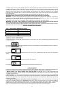
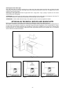
LOCATION AND AERATION
The gas cooking appliances must always evacuate the combustion products by means of hoods connected to chimneys,
flues or directly outside (see Fig. 4). If a hood cannot be installed, it is possible to use a fan installed on a window or
directly facing outdoors, to be operated together with the appliance (see Fig. 5), provided that there is strict compliance
with the ventilation regulations.
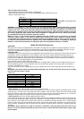
HEIGHT ADJUSTABLE LEGS (Fig.6)
Legs are packed in the top box.
Legs should be installed with the appliance being near the location of final installation, they are not secure for long
transport. After unpacking the range, raise it about a foot to insert the legs in their bases assembled on the lower part of
the cooker and lower the range gently to keep any undue strain from legs and mounting hardware. It is recommended to
use a pallet or lift jack instead of tilting the unit.
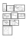
BACKGUARD INSTALLATION INSTRUCTION
1) Remove n°2 screws fixing worktop as shown in fig.7
2) Place front part of the backguard and attach it from bottom side with the two removed screws (point 2) as shown in
fig .8
3) Fix the front part of the backguard with the screws supplied with the backguard kit (fig.9)
4) Assemble back part with front part of the backguard and fix them with a screws supplied with the backguard kit
(fig.10)
APPLIANCE GAS CONNECTION
Before connecting the appliance to the gas network, make sure that the data on the label attached to the food
warmer drawer or on the back of the cooker are compatible with what is indicated for the gas distribution
network.
A label attached to the last page of this handbook and in the food warmer drawer (or on the back) of the
appliance indicates the appliance adjustment conditions: type of gas and operating pressure.
IMPORTANT: This appliance must be installed in compliance with current national standards in force and used
only in a well-ventilated room.
WARNING: It should be recalled that the appliance utilises a threaded 1/2" gas cylindrical male fitting according
to UNI-ISO 228-1.
To connect the appliance to the gas network with a flexible rubber hose, a supplemental hose nipple fitting is
needed (see Fig. 7) which is supplied with the appliance.
ADAPTATION TO DIFFERENT TYPES OF GAS FOR COOKER TYPE M6V
Before performing any maintenance operation, disconnect the appliance from the gas supply and electricity
network.
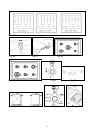
REPLACING THE NOZZLES TO OPERATE WITH ANOTHER TYPE OF GAS FOR COOKER TYPE M6V:
Follow the instructions below to change the burner nozzles on the work surface:
1) Pull out the plug from the electric outlet to avoid any type of electric contact.
2) Remove the grids from the work surface.
3) Remove the burners.
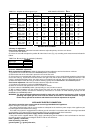
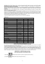
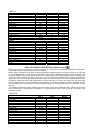
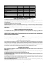
4) Unscrew the nozzles using a 7 mm spanner, and replace them (Fig.12) with those needed for the new type of gas
according to what is indicated in Table 1.
Follow the instructions below to change the oven burner nozzle:
1) Remove the oven level (Fig. 13).
2) Loosen the screw V and pull out the burner from the support being careful not to damage the ignition plug and the
thermocouple (Fig. 14).
3) Unscrew the nozzle R using a 10 mm spanner and replace it with the nozzle needed for the new type of gas according
to what is indicated in Table 1
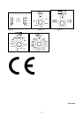
WARNING: After completing the above-mentioned replacements, the technician must adjust the burners, as
described in the paragraph below, seal any adjustment and pre-adjustment devices and apply the label on the
appliance, to replace the existing one, corresponding to the new gas adjustment. This label is contained in the
spare nozzle bag.