


4
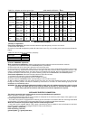
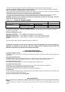
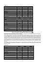
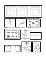
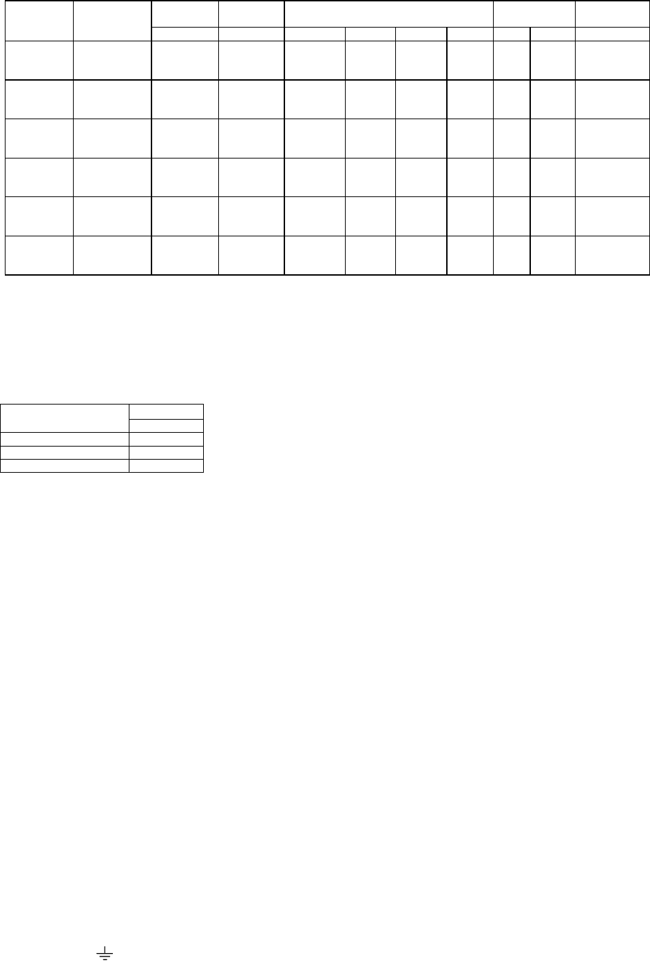
TABLE N°1: Adaption to various types of gas APPLIANCE CATEGORY: II2H3+
Burner Types of Gas Pressure Nozzle
Diameter
Rater Capacity Reduced
Capacity
by-pass
Diameter
mbar 1/100 mm. g/h l/h kw kcal/h kw kcal/h 1/100 mm.
Natural G20 20 72 - 95 1 860 0,48 413 34 reg.
Auxiliary Butane G30 30 50 73 - 1 860 0,48 413 34
Propane G31 37 50 71 - 1 860 0,48 413 34
Natural G20 20 97 - 167 1,75 1505 0,6 516 36 reg.
Semi-Rapid Butane G30 30 65 127 - 1,75 1505 0,6 516 36
Propane G31 37 65 125 - 1,75 1505 0,6 516 36
Natural G20 20 115 - 286 3 2580 1,05 903 52 reg.
Rapid Butane G30 30 85 218 - 3 2580 1,05 903 52
Propane G31 37 85 214 - 3 2580 1,05 903 52
Dual Natural G20 20 72 - 95 1 860 0,48 413 34 reg.
Inner Butane G30 30 46 73 - 1 860 0,48 413 34
Propane G31 37 46 71 - 1 860 0,48 413 34
Dual Natural G20 20 102 - 334 3,5 3010 1,8 1548 65 reg.
Outer Butane G30 30 66 254 - 3,5 3010 1,8 1548 65
Propane G31 37 66 250 - 3,5 3010 1,8 1548 65
Natural G20 20 125 - 286 3 2580 1 860 48 reg.
Oven Butane G30 30 85 218 - 3 2580 1 860 48
Propane G31 37 85 214 - 3 2580 1 860 48
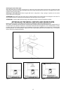
BURNER ADJUSTMENT
1)Primary air adjustment:
Oven burner adjustment: follow the instructions below to adjust the primary air for the over burner:
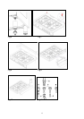
1) Remove the oven bottom.
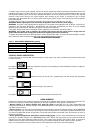
2) Loosen the screw P and adjust the position X of the Venturi cone (Fig. 15) according to the measurements indicated in
table 2.
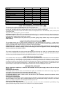
TABLE N°2: Burner primary air regulation (indicative)
BURNER
Type of gas Oven (mm)
Natural G20 fully open
Butane G30 fully open
Propane G31 fully open
2) Burner "MINIMUM" adjustment:
Work surface burner adjustment: follow the instructions below to adjust the work surface burner minimum:
1) Light the burner and set the knob to the MINIMUM position (small flame).
2) Remove the knob of the valve that is press fit on the rod of that valve.
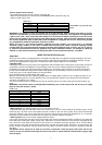
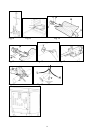
3) If the cooker is not equipped with safety valves on the surface burners, insert a small slotted screwdriver into the hole
on the valve rod (Fig. 16) and turn the choke screw to the right or left until the burner flame is adjusted to minimum. If the
cooker is equipped with safety valves, the choke valve is not located in the rod hole, but on the valve body (see fig. 17).
4) Make sure that the flame does not go out when switching quickly from the MAXIMUM to the MINIMUM position.
Oven burner adjustment: follow the instructions below to adjust the minimum:
1) Light the burner setting the knob to the MAXIMUM position.
2) Close the oven door and operate the oven for at least 10 minutes.
3) Set the knob to the MINIMUM position (corresponding to 120°) and then remove it.
4) With a slotted screwdriver turn the choking screw (see figure 18) and, while observing the flame at the same time
through the cooker porthole, evaluate the consistency of the flame so it remains on when switching quickly from the
MINIMUM to the MAXIMUM position.
WARNING: The above-mentioned adjustment should be made only with methane gas burners, while for those
operating with liquid gas the screw must be locked at the end in a clockwise direction. The grill
burner always operates at maximum and therefore no minimum adjustment is required.
APPLIANCE ELECTRIC CONNECTION:
The electric connection must comply with the current legal standards and regulations.
Before making the connection, check that:
- The system electrical rating and the current outlets are adequate for the maximum power output of the appliance (see
the label applied to the bottom of the casing).
- The outlet or the system is equipped with an efficient ground connection in accordance with the current legal standards
and regulations. The company will not be responsible for the non-compliance with these instructions.
When the connection to the power supply network is made using an outlet:
- If the power cord is supplied without a plug, apply a standard plug that is suitable for the load indicated on the label.
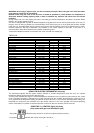
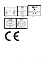
Connect the wires according to the diagram shown in FIG.19 and check that:
letter L (phase) = brown wire;
letter N (neutral) = blue wire;
ground symbol
= green-yellow wire;