


6
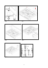
To replace parts such as nozzle supports, valves and electric components follow the procedure described in the burner
adjustment paragraph. To replace the valve or the gas thermostat, it is also necessary to disassemble the two rear gas
train brackets, loosening the 4 screws (2 per bracket) that attach it to the rest of the cooker and, unscrew the nuts that
attach the front burner valves to the control support, after removing all the knobs. To replace the gas or electric
thermostat, also disassemble the rear cooker guard, loosening the relative screws, to be able to pull out and reposition
the thermostat bulb.
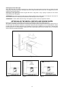
To replace the oven bulb, just unscrew the protection cap that projects out inside the oven. (Fig.20)
WARNING: Before replacing the bulb, disconnect the appliance from the electric power supply.
WARNING: The power cord supplied with the appliance is connected to that appliance with an X type connection (in
compliance with standards EN 60335-1, EN 60335-2-6 and subsequent amendments) for which it can be installed
without the use of special tools, with the same type of cord as the one installed.
If the power cord becomes worn or damaged, replace it based on the information reported in table 3 .
WARNING: If the power cord is replaced, the installer shall ensure that the ground cable is longer than the
phase cables and also shall comply with the warnings regarding the electric connection.
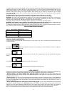
To replace the power cable, lift the terminal board’s cover and replace the cable. To access the terminal board in cookers
with a 3x2.5mm² cable, the back panel on the rear of the appliance must be removed.
USE AND MAINTENANCE MANUAL
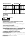
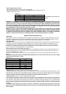
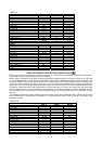
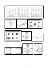
Table 4 GAS BURNER DIMENSION (fig.22-23)
Burner Dimension (mm)
Auxiliary Ø 50
Semi-rapid Ø 70
Rapid Ø 95
Dual Ø 140
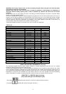
CONTROL PANEL DESCRIPTION
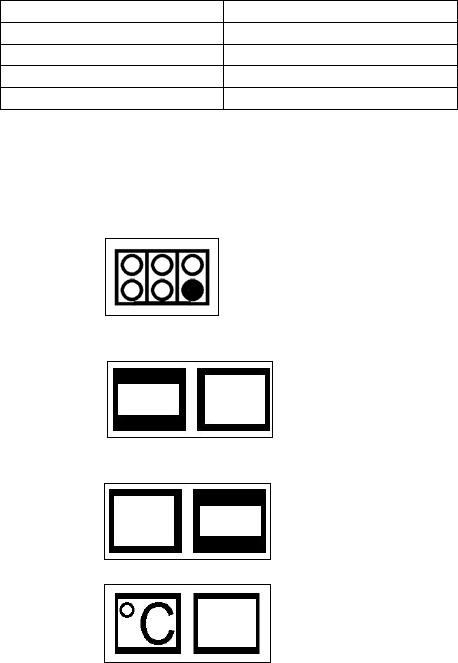
On the control panel, small symbols show the function of each knob or key. Here as follows are the several controls that
a cooker can have:
the symbol
shows the disposition of burners on the worktop, the full dot identifies the burner in object (in
this case the front burner on the right).
the symbol
shows the running of any left oven (ventilated gas oven with electric grill, 9 positions
switch)
the symbol
shows the running of any right oven
the symbol
shows the electric thermostat for electric left oven
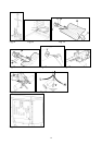
USING BURNERS
A diagram is etched on the control panel above each knob which indicates which burner corresponds to that knob. The
burners can be ignited in different ways depending on the type of appliance and its specific characteristics:
- Manual lighting (it is always possible even when the power is cut off): Turn the knob anticlockwise that
corresponds to the burner selected, setting it to the MAXIMUM position at the etched star (large flame Fig.24) and place
a lit match up to the burner.
- Electric ignition:
Turn the knob counterclockwise that corresponds to the burner selected, setting it to the MAXIMUM
position (large flame Fig. 24) and keep on pressing the knob in correspondence of the ignition symbol marked with a star
(for cookers equipped with ignition trough knob) or press the ignition button marked with a star and release it as soon as
the burner has ignited.
- Burner ignition equipped with safety device (thermocouple)(fig.25): Turn the knob anticlockwise that corresponds
to the burner selected, setting it to the MAXIMUM position at the etched star (large flame Fig. 24), press the knob and
activate one of the above-mentioned ignition devices. Once ignited, keep pressing the knob for about 10 seconds to
allow the flame to heat the thermocouple. If the burner goes out after releasing the knob, repeat the entire operation.
Note: It is recommended not to try to ignite a burner if the relative flame cap is not in the correct position.