


Installation
10
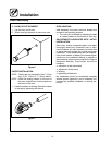
Electrical Connection
Wiring diagrams are located in the control com-
partment area.
Ovens are supplied for operation in several volt-
age choices, single or three phase grounded cir-
cuits.
The electric motor, indicator lights and related
switches are interconnected through the one pow-
er source supplied to the oven.
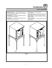
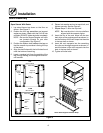
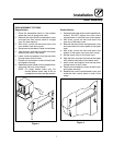
1. The supply conduit enters through the rear of
the oven and electrical block secured to the
perforated panel at the back of the control
compartment.
THE BLODGETT OVEN COMPANY CANNOT AS-
SUME RESPONSIBILITY FOR LOSS OR DAMAGE
SUFFERED AS A RESULT OF IMPROPER INSTAL-
LA TION.
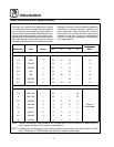
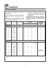
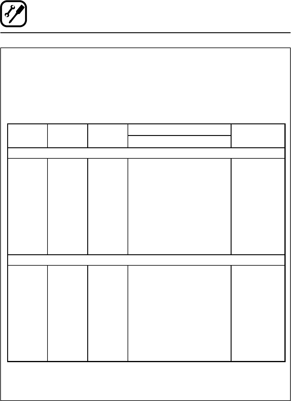
Amperes
Electrical
C
o
n
n
e
c
t
i
o
n
KW/Section Volts Phase
L1 L2 L3 N
C
onnect
i
on
AWG*
60 HZ UNITS
5.6 208 1 27 --- 27 --- 8
5.6 208 3 24 12 15 --- 10
5.6 220-240 1 24 --- 2 4 --- 8
5.6 220-240 3 21 11 14 --- 10
8.0 208 1 35 --- 3 5 --- 6
8.0 208 3 22 20 21 --- 10
8.0 220-240 1 32 --- 3 2 --- 6
8.0 220-240 3 20 18 19 --- 10
50 HZ UNITS
5.6 220---240 1 24 --- --- 24
8 220---240 1 35 --- --- 3 5
5.6 220/380 3 10 882
8 220/380 3 14 12 12 2
5.6 240/415 3 10 773
Size per
l
l
d
8 240/415 3 13 11 11 2
local codes
5.6 230/400 3 9 881
8 230/400 3 13 11 11 2