39
2
2
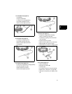
1. Connect stator wire harness to regulator-
rectifier.
2. Insert RED test lead into 10 Amp
receptacle in meter.
3. Insert BLACK test lead into COM
receptacle in meter.
4. Rotate selector to DC Amps position.
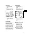
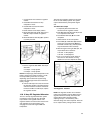
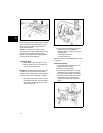
5. Attach RED test lead clip (A, Figure 27) to
RED DC output terminal on regulator-
rectifier.
6. Attach BLACK test lead clip (B) to positive
(+) battery terminal.
Figure 27
7. Run the engine at 3600 RPM. The output
should be:
• 3-5 Amps - 5 Amp System
• 3-9 Amps - 9 Amp System
NOTE: The amperage produced depends on the
battery voltage. If the battery is below 11 Volts,
the output reading would be 5 or 9 Amps,
depending upon the alternator system being
tested. The amperage will be less at maximum
battery voltage.
8. If NO or LOW output is found, be sure that
the regulator-rectifier is grounded properly
and all connections are clean and secure.
If there is still NO or LOW output, replace
the regulator-rectifier.
10 & 16 Amp DC Regulated Alternator
The 10 & 16 Amp regulated alternator system
provides AC current through two YELLOW
output leads to the regulator-rectifier. The
regulator-rectifier converts the AC current to DC
and regulates current to the battery. The
charging rate varies with engine RPM and
temperature.
The stator and regulator-rectifier are the same
for the 10 and 16 Amp systems. The system
output is determined by the flywheel magnet
size.
Test Alternator Output
1. Temporarily disconnect stator wire
harness from the regulator-rectifier.
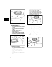
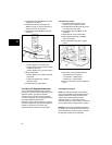
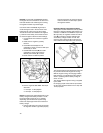
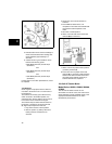
2. Insert RED test lead (A, Figure 28) into the
V Ω receptacle in the meter.
3. Insert BLACK test lead (B) into COM
receptacle.
4. Rotate selector to AC Volts position.
5. Insert RED (A) and BLACK (B) test lead
probes into output terminals (D & E) in
YELLOW connector (C). (Test clip leads
may be attached to either terminal).
6. With the engine running at 3600 rpm, the
output should be no less than:
• 20 volts - 10 Amp System
• 30 volts - 16 Amp System
7. If No or Low output is found, check for
bare wires or other defects. If wiring
defects are not found, replace the stator.
Figure 28
Test Regulator - Rectifier
NOTE: The regulator-rectifier will not function
unless it is grounded to engine. Make sure the
regulator-rectifier is securely mounted to the
engine. When testing regulator-rectifier
amperage output, a 12 Volt battery with a
minimum charge of 5 Volts is required. There will
be no output if battery voltage is below 5 Volts.


