


5.4 INSTALLATION OF THE OPTIONAL WALL CONTROLS
(CONTROLS C12 / CM AND C34 / CMR) (CONT’D)
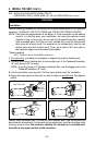
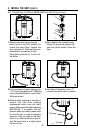
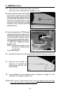
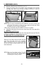
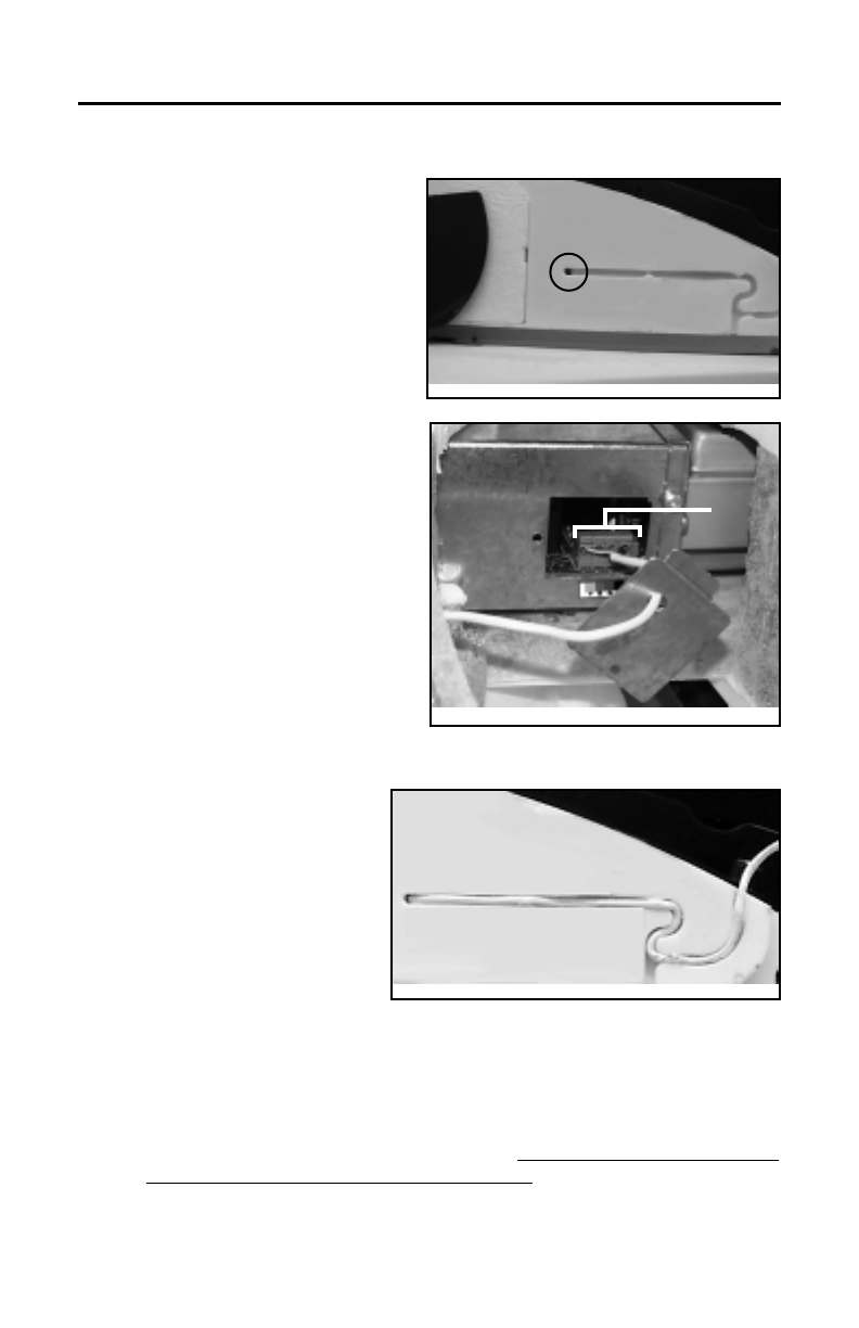
8. Using a small rod, pierce a hole through
the unit at the end of the wire channel.
(See picture beside.) Splice back the
end of the cable to access the 4 wires.
Remove the insulated sleeve of each
wire ends. Insert the end of the cable
through the unit, using the small hole
previously done.
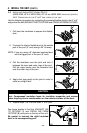
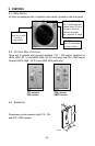
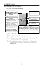
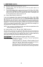
9. In order to access the unit PCB terminals,
remove the side door located on the
electrical box and punch out its knock
out. Run the cable through the knock-out
hole and connect each wire in their
corresponding terminal (YELLOW in
‘’Y’’, RED in ‘’R’’, GREEN in ‘’G’’and
BLACK in ‘’B’’).
NOTE: Push forward slightly on the
little tabs (1) to ease insertion
of each wires.
See picture beside.
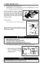
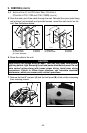
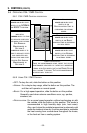
10. Reinstall the side door on the electrical box and the 8’’ oval port on the unit.
11. Route the wire through its
channel and reinstall the
front panel on the unit. See
picture beside.
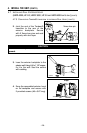
12. If the installation is not completed, return to Section 4 on page 19. If the
installation is completed, plug the unit.
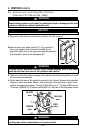
NOTE: When using an optional wall control, the main s
witch on the unit must
always be positioned to NORMAL/REMOTE.
5. CONTROLS (CONT’D)
VD0089
- 31 -
VD0088
VE0049
1