


13
SERVICE
This section provides procedures for testing and
replacing various major components used in this
dispenser should service become necessary. Refer to
Troubleshooting
for assistance in determining the
cause of any problem.
WARNING - Inspection, testing, and repair of electri-
cal equipment should be performed only by qualified
service personnel. The dispenser should be un-
plugged when servicing, except when electrical tests
are required and the test procedure specifically states
to plug-in the dispenser.
COMPONENT ACCESS
WARNING - Disconnect the dispenser from the power
source before the removal of any panel or the replace-
ment of any component.
All components are accessible by opening the
door, removal of the door panels, dispenser top cov-
ers, hoppers, hopper support plate, splash
guard,splash panel w/drip tray, lower front access
panel, side and rear access covers.
Contents
Auger Drive Components......................................13
Auger Motor .........................................................15
Ballast...................................................................16
Control Board .......................................................17
Control Thermostat...............................................19
Dispense Switch ...................................................20
Fan........................................................................21
Frother ................................................................. 22
Hot/Cold Switch....................................................24
Increase/Decrease Switch.....................................25
Lamp Holder .........................................................26
Lamp ....................................................................26
Lamp Starter and Socket ......................................27
Limit Thermostat ..................................................27
Overflow Protection Switch ..................................28
Rinse/Run Switch .................................................29
Solenoid (Cold Drink - Optional)...........................30
Solenoid (Dispense) .............................................31
Solenoid (Inlet) .....................................................32
Tank Heater ..........................................................33
Tank Heater Switch...............................................34
Transformer..........................................................35
Whipper Motor .....................................................22
Wiring Diagram ....................................................37
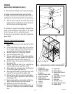
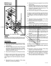
FIG. 1 AUGER DRIVE COMPONENTS
Location
The auger components are located inside
the bottom part of the hopper except for the auger
drive bracket, washer and locknut, which are located
on the outside bottom rear of the hopper. The auger
motors are located on the rear of the auger motor
mounting panel. Refer to Fig. 2 for disassembly and
assembly.
Test Procedures - Auger motors
1. Disconnect the dispenser from the power source.
2. Disconnect the wires from the motor to be tested.
3. Check the voltage across the positive (white/blue)
wire for the right motor, positive (white/orange)
wire for the center motor or the positive (white/
red) wire for the left motor and the negative
(green) wire with a voltmeter. With the rinse/run
switch in the run position press and hold the
appropriate dispense switch. Connect the dis-
penser to the power supply. After a .6 second
delay the indication must be 4.0 to 24.5 volts dc.
AUGER DRIVE COMPONENTS
P1637.40