


18
J
4
J
2
J
3
J
1
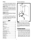
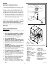
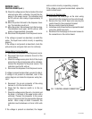
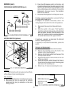
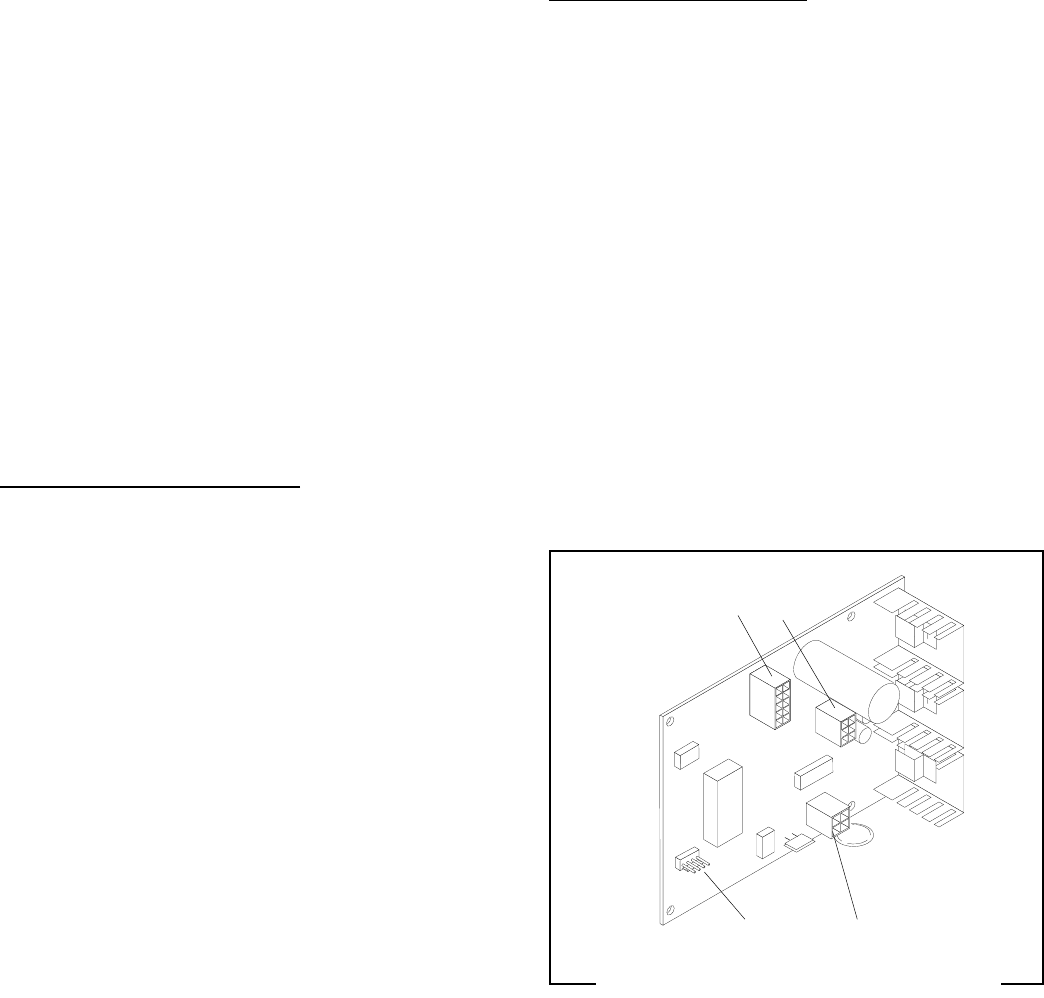
J1 J4
J2 J3
FIG. 7 CONTROL BOARD CONNECTORS
P1640
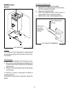
19. Check the voltage across the terminals of the inlet
solenoid valve with a voltmeter. Connect the dis-
penser to the power source. The indication must
be 120 volts ac after a delay of approximately 10
seconds.
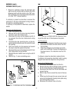
20. Move the probe’s flat end to the dispenser hous-
ing. The indication must be 0.
21. Move the probe’s flat end away from the housing.
The indication must, again, be 120 volts ac after
a delay of approximately 5 seconds.
22. Disconnect the dispenser from the power source.
If the voltage is present as described, re-install the
probe. The liquid level control circuitry is operating
properly.
If the voltage is not present as described, check the
pink probe wire and green tank wire for continuity.
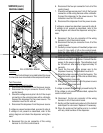
Hopper Motor Control Circuitry:
1. Disconnect the dispenser from the power source.
2. Disconnect the six pin connector from J3 of the
control board.
3. Check the voltage across pins 5 & 6 of the six pin
connector on the wiring harness with a voltmeter.
Connect the dispenser to the power source. The
indication must be 24 volts ac.
4. Disconnect the dispenser from the power source.
If voltage is present as described, proceed to step 5.
If voltage is not present as described, refer to the
wiring diagram and check the dispenser wiring har-
ness.
5. Reconnect the six pin connector of the wiring
harness to J3 of the control board.
6. Check that the rinse/run switch is in the run
position.
7. Check the voltage across the red (+) terminal and
the black (-) terminal of the auger motor with a
voltmeter. Connect the dispenser to the power
source. Press and hold the appropriate dispense
switch. After a delay of about .6 seconds, the
indication must be between +4.0 and +24.5 volts
dc.
If the voltage is present as described, the hopper
SERVICE (cont.)
CONTROL BOARD (cont.)
motor control circuitry is operating properly.
If the voltage is not present as described, replace the
control circuit board.
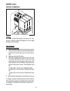
Removal and Replacement:
1. Disconnect the three plugs on the main wiring
harness from the connectors on the control board.
2. Remove the four #6-32 keps nuts securing the
control board to the component bracket.
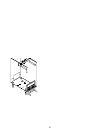
3. Remove control board and discard.
4. Install new control board on the component bracket
using four #6-32 keps nuts.
5. Reconnect the three plugs on the main harness to
the connectors on the control board.
29170 091598