


21
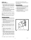
FAN
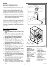
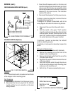
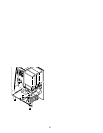
FIG. 12 FAN
P1436
Location:
The fan is located inside the dispenser hous-
ing on the right rear of the dispenser base plate.
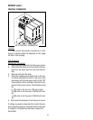
Test Procedures:
1. Disconnect the dispenser from the power source.
2. Disconnect the black and white wires from the
fan terminals.
3. Check the voltage across the black and white
wires with a voltmeter. Connect the dispenser to
the power source. The indication must be 120
volts ac.
If voltage is present as described, replace the fan
If voltage is not present as described, refer to wiring
diagram and check the dispenser wiring harness.
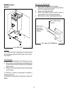
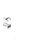
Removal and Replacement:
1. Disconnect the vacuum hose from the fan.
2. Remove the two #8-32 locking screws securing
the fan to the dispenser housing base plate.
3. Disconnect the wires from the fan terminals and
discard the fan
4. Refer to Fig.13 and connect the wires to the new
fan.
5. Install new fan through the rear access hole and
secure to the dispenser housing base plate using
two #8-32 locking screws.
6. Reconnect the vacuum hose to the fan.
SERVICE (cont.)
7. Check for continuity across the terminals (top
right to top left; bottom right to bottom left) of the
dispense switch with the switch in the “ON” posi-
tion. Continuity must not present when the switch
is in thhe “OFF” released position.
If continuity is present as described, reconnect the
connector to the door interconnect wiring harness,
the switch is operating properly.
If continuity is not present as described, replace the
switch.
Removal and Replacement:
1. Open the dispenser door.
2. Remove the five #6-32 screws securing the bot-
tom door cover and remove cover.
3. Disconnect the wires on the dispense switch to
be removed from the door interconnect wiring
harness.
4. Compress the clips inside the door on the dis-
pense switch and gently push the switch through
the opening.
5. Push new switch into the opening and spread
the clips to hold the switch in the door.
6. Reconnect the wires to the dispense switch from
door interconnect wiring harness.
7. Reinstall the door bottom cover using five #6-32
screws.
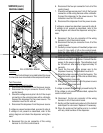
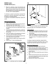
8. Refer to Fig. 11 when reinstalling wires.
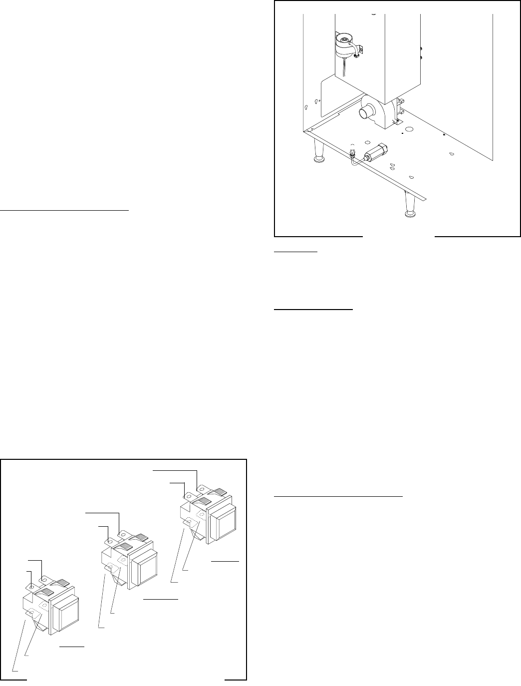
P1449
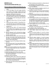
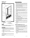
FIG. 11 DISPENSE SWITCH TERMINALS
LEFT
CENTER
RIGHT
BLK
RED/BLK
BLK
RED/WHI
BLK
RED
DISPENSE SWITCH (cont.)
ORN
BLU/WHI
ORN
BLK/WHI
ORN
BLU/BLK