


12
SERVICE (cont.)
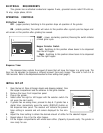
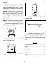
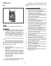
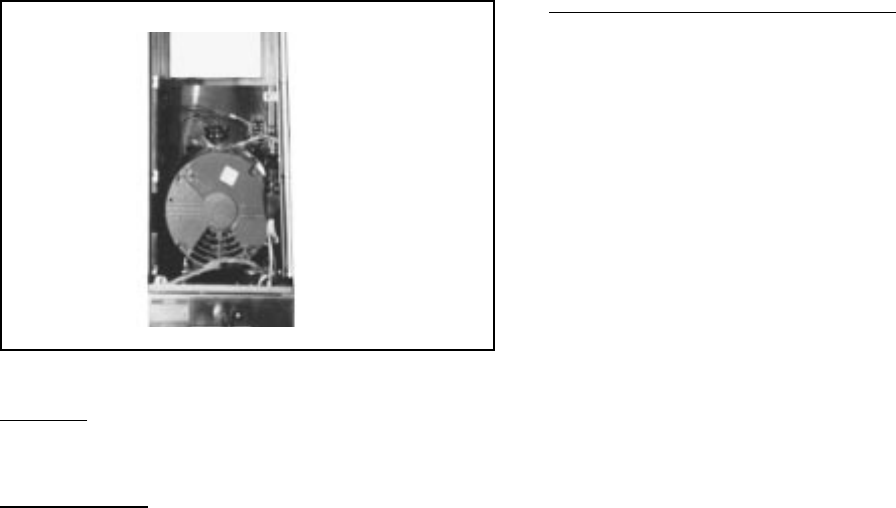
Motor
Location:
The motor is located in the upper wrapper.
Test Procedure:
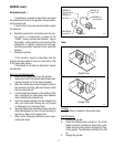
1. Remove the cover plate located on the right side
of the housing. Press the red “Reset” button vis-
ible through the opening. Listen carefully for a
“click”. This resets the motor protection circuit
and may indicate that something other than cof-
fee was inserted into the hopper for grinding.
If the grinder remains unable to start, proceed
to #2.
If the grinder stops operating shortly after start-
ing, refer to the removal and replacement steps to
gain access to the grind chamber. Remove any for-
eign materials that may be found.
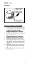
2. Unplug the grinder.
3. Remove the electrical access panel at the rear
of the motor.
4. Check the voltage across terminals L1 & L2 of the
motor with a voltmeter when the Off/On/Start
switch is pressed to the “START” (lower) position
and released. Plug-in the grinder. The indication
must be 120 volts ac.
5. Unplug the grinder
If voltage is present as described and the grinder
remains unable to start, replace the motor.
If voltage is not present as described, refer to
the
Wiring Diagrams,
and check the grinder wiring
harness.
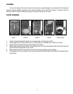
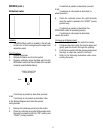
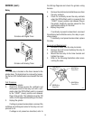
Removal and Replacement - MOTOR
1. Remove all wires from the solenoids and lift the
hopper assy out of the grinder housing.
2. Remove all wires from the Off/On/Start switch,
motor, and motor mounting plate.
3. The entire wiring harness must be fed into the
bottom of the grinder housing through the hole
in the motor mounting plate.
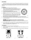
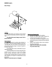
4. Remove both 6-32 screws beneath the upper
front inspection panel.
5. Remove the six 10-32, slotted, hex head screws
on top of the motor mounting plate.
6. Slowly slide the assembly out the rear of the
grinder housing. The mounting plate may have
to be raised to gain clearance for the motor hard-
ware and wiring harness bushing.
7. Remove the four 5/16"-18 bolts and nuts to sepa-
rate the motor from the mounting plate.
8. Mount the new motor and tighten the four bolts
and nuts. They should be tightened approxi-
mately one full turn past snug.
9. Slide the motor mounting plate into the rear of
the grinder housing.
10. Feed the wiring harness into the top of the hous-
ing through the hole in the motor plate.
11. Reinstall the six 10-32 hex head screws through
the motor plate and the two 6-32 slotted head
screws through the housing.
12. Reattach the green wire to the 10-32 stud on
the motor mounting plate.
13. Refer to the
Off/On/Start switch
section when
reconnecting the switch wires.
14. Refer to the
Solenoid
section when reconnect-
ing the solenoid wires.
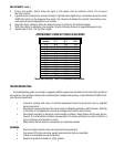
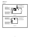
15. Refer to the following illustration when recon-
necting the wires.
P607