


18
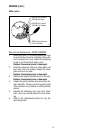
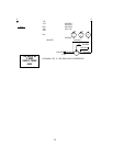
4. Check the voltage across contacts 2 & 6 of the
larger connector on the timer board with a volt-
meter when the control switch is in any position
except “OFF” (center). Plug-in the grinder. The in-
dication must be 120 volts ac.
5. Unplug the grinder.
If voltage is present as described, proceed to
#6.
If voltage is not present as described, refer to
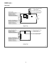
the
Wiring Diagram
and check the grinder wiring har-
ness.
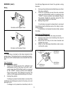
6. Check the voltage across contacts 3 & 7 of the
larger connector on the timer board with a volt-
meter after the Off/On/Start switch has been mo-
mentarily pressed to “START” (lower) position and
released. Plug-in the grinder. The indication must
be 120 volts ac.
7. Unplug the grinder.
If voltage is present as described, proceed to
#8.
If voltage is not present as described, replace
the timer.
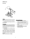
8. Check the voltage across contacts 4 & 7 of the
larger connector on the timer board with a volt-
meter after the hopper selector switch is set to
the left position and the Off/On/Start switch has
been momentarily pressed to the “START”
(lower) position and released. Plug-in the
grinder. The indication must be 120 volts ac and
should remain for the approximate timer set-
ting.
9. Unplug the grinder.
If voltage is present as described, proceed to
#10.
If voltage is not present as described, replace
the timer.
10. Check the voltage across contacts 5 & 7 of the
larger connector on the timer board with a volt-
meter after the hopper selector switch is set to
the right position and the Off/On/Start switch
has been momentarily pressed to the right
“START” (lower) position and released. Plug-in
the grinder. The indication must be 120 volts ac
and should remain for the approximate timer
setting.
11. Unplug the grinder.
If voltage is present as described, the timer is
operating properly.
If voltage is not present as described, replace
the timer.
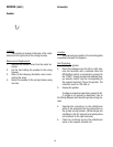
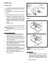
Removal and Replacement:
1. Separate the grinder wiring harness connectors
from the timer circuit board.
2. Remove the relay from the timer bracket.
3. Attach the relay to the new timer bracket.
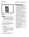
4. Refer to the following illustration when reattach-
ing the connectors.
5. Refer to the
Adjustments
section to reset the vol-
ume dispensed.
SERVICE (cont.)
Timer (cont.)