


15
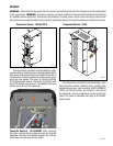
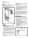
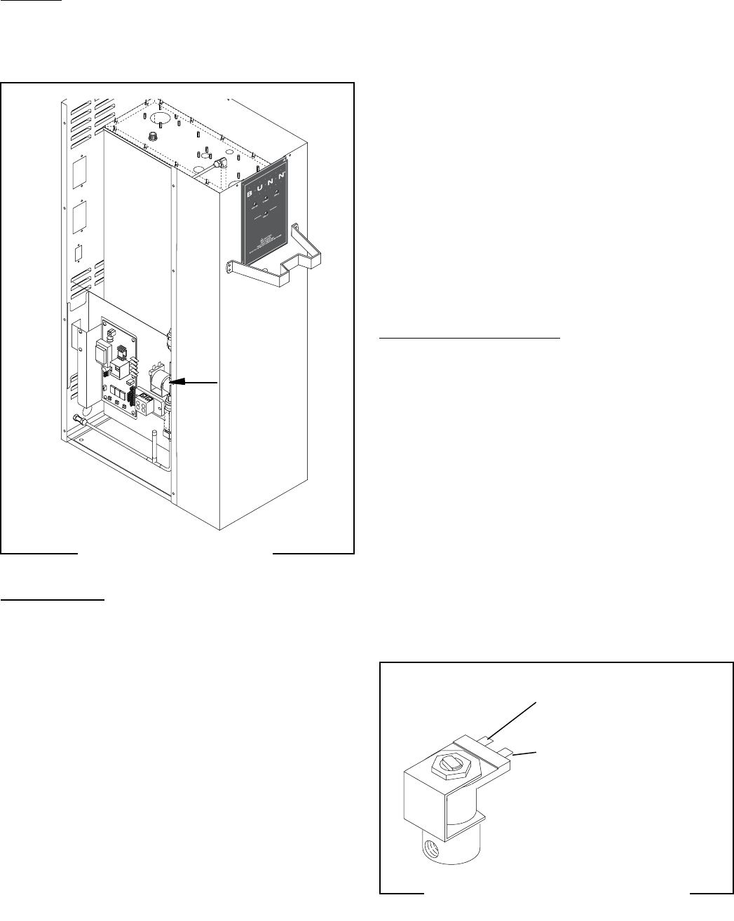
Solenoid Valve (Early Models)
Location:
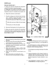
The solenoid valve is located behind the large access
panel on the left side of the dispenser.
To test the solenoid valve, access will also be needed
to the electronic control board.
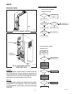
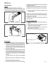
BUNN
90 psig max operating pressure
Strainer/Flow Control # 22300.0750
(Repl. Flow Washer #20526.0750)
(Repl. Screen #23721.0000)
.750 gpm FLOW
P1994
FIG. 15a SOLENOID VALVE
SERVICE (cont.)
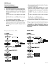
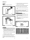
Test Procedure:
1. Disconnect the dispenser from the power source
and turn off the water supply to the dispenser.
2. Remove the pink wire from terminal 5 of the elec-
tronic control board.
3. Check the voltage across the solenoid valve coil
terminals with a voltmeter. Connect the dispenser
to the power source. The indication must be 200
to 240 volts ac for 200 to 240 volt models after a
delay of approximately 5 seconds.
4. Disconnect the dispenser from the power source.
If voltage was present as described, proceed to #5.
If voltage was not present as described, refer to the Wir-
ing Diagrams and check the dispenser wiring harness.
5. Remove both wires from the solenoid valve coil
terminals.
6. Check for continuity across the solenoid valve coil
terminals.
If continuity is present as described, reconnect the
wires and proceed to #7.
If continuity is not present as described, replace the
solenoid valve coil.
7. Check the solenoid valve for coil action. Connect
the dispenser to the power source. Listen carefully
in the vicinity of the solenoid valve for a “clicking”
sound after approximately 5 seconds, as the coil
magnet attracts the plunger.
8. Disconnect the dispenser from the power source.
9. Reconnect the pink wire to terminal 5 of the elec-
tronic control board.
If the sound was heard as described and water will
not pass through the solenoid valve, there may be a
blockage in the water line before or after the solenoid
valve or the solenoid valve may require inspection for
wear and removal of waterborne particles.
If the sound was not heard as described, replace the
solenoid valve.
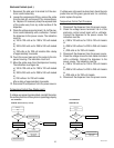
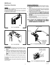
Removal and Replacement:
1. Remove all wires from the solenoid valve coil.
2. Turn off the water supply to the dispenser.
3. Disconnect the water lines to and from the solenoid
valve.
4. Remove the two 8-32 slotted-head screws holding
the solenoid valve and mounting bracket to the
component bracket.
5. Lift out the solenoid valve.
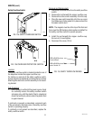
6. Remove the two 10-32 slotted-head screws holding
the solenoid valve to its mounting bracket.
7. Securely install the new solenoid valve to its mount-
ing bracket. The direction of flow arrow must be
pointing towards the tank lid.
8. Attach the solenoid valve and mounting bracket to
the component bracket.
9. Securely fasten the water lines to and from the
solenoid valve.
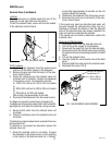
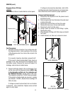
10. Reconnect the wires, FIG. 8.
WHI/BLU to Contol
Board T1
RED to Terminal Block
RED to Control Board T4
P1779
FIG. 15b SOLENOID VALVE WIRING
42311 071310
H 10