16
SERVICE (cont.)
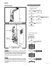
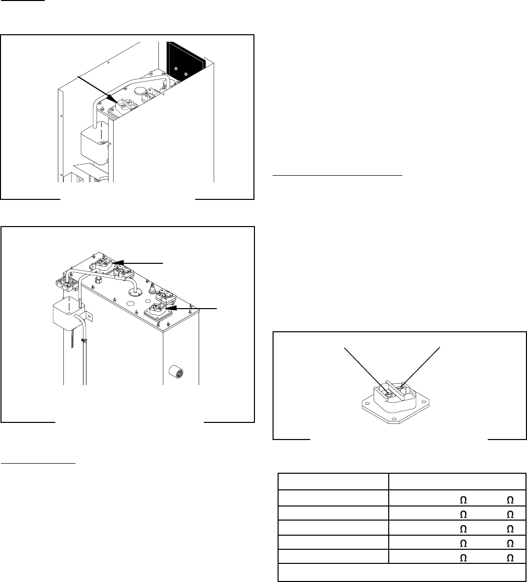
Tank Heater
Location:
The tank heater is located in the tank lid.
Test Procedure:
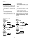
1. Disconnect the dispenser from the power source.
2. Check the voltage across the terminals of the tank
heater with a voltmeter. Connect the dispenser to
the power source. The indication must be:
a.) 100 to 120 volts ac for 100 to 120 volt models
or
b.) 200 to 240 volts ac for 200 to 240 volt models
or
c.) 230 volts ac for 230 volt models.
3. Disconnect the dispenser from the power source.
If voltage is present as described, proceed to #4.
If voltage is not present as described, replace the tank
heater.
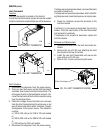
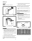
FIG. 16a TANK HEATER
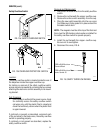
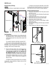
FIG. 16c TANK HEATER WIRING
T
his equipment is to be installed to
comply with the Basic Plumbing Code of
the Building Officials and Code
Administrators International, Inc. (BOCA)
and
the Food Service Sanitation Manual
of the Food and Drug Administr
atio
n (FDA).
BLK to Limit
Thermostat
BLU to Control
Board Relay
P1780
P4093
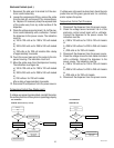
4. Remove the tank heater from the tank lid and in-
spect it for cracks in the sheath.
If the sheath shows no sign of damage, proceed to #5.
If the sheath is damaged, replace the tank heater.
5. Check for continuity across the tank heater termi-
nals.
If continuity is present as described, reinstall the tank
heater. The tank heater is operating properly.
If continuity is not present as described, replace the
tank heater.
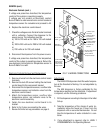
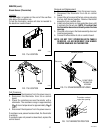
Removal and Replacement:
1. Remove the wires to the tank heater.
2. Remove the 8-32 nuts from the tank heater flange.
3. Remove the tank heater.
4. Inspect the tank heater gasket and replace if neces-
sary.
5. Securely install the new tank heater. Be certain of
a watertight seal.
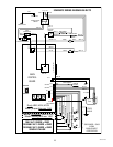
6. Reconnect the wires, FIG. 10.
P1993
FIG. 16b TANK HEATER
42311 071310
1800W-120V 07.44 - 08.67
4000W-240V 13.43 - 15.51
4000W-208V 10.09 - 11.99
6000W-240V 08.85 - 10.23
6000W-208V 06.67 - 07.70
HEATER RESISTANCE
TERMINAL TO SHEATH - INFINITE (OPEN)
H 10
H 5


