7
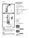
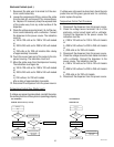
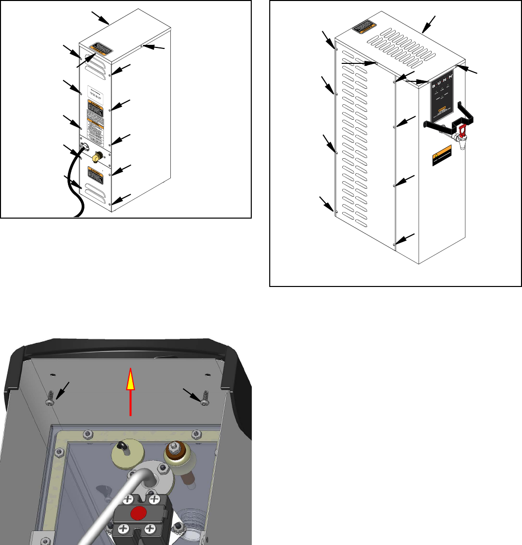
Faceplate Removal - H5 ELEMENT: After removing
top cover, remove the two upper screws securing the
faceplate. Carefully lift faceplate straight up until the
three lower screws clear the key holes.
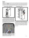
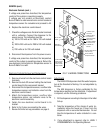
The check valve, electronic control assembly, safety
overflow switch, solenoid valve, overflow tube tempera-
ture sensor and terminal block are located at the rear of
the dispenser. Access is gained by removing the upper
and lower rear panels. The upper is attached with six
8-32 slotted-head screws. The lower is attached with
four 8-32 slotted-head screws. The middle panel must
not be removed from the dispenser.
P1770.30
42311 022311
WARNING
Very Hot Water
Use With Care!
!
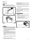
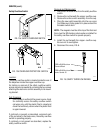
The check valve, electronic control assembly, over-
flow protection switch, solenoid valve, overflow tube
temperature sensor, triac assembly (EARLY MODELS
ONLY) and terminal block are located on the side of
the dispenser. Access is gained by removing the side
panel. The panel is attached with eight 8-32 slotted-
head screws.
P878.30
SERVICE
WARNING – Disconnect the dispenser from the power source before the removal of any panel or the replacement
of any component. WARNING - Inspection, testing, and repair of electrical equipment should be performed only
by qualified service personnel. Disconnect the dispenser fromthe power source when servicing, except when
electrical tests are required and the test procedure specifically states to connect the dispenser to the power source.
Component Access - H5E/DV-PC/X Component Access - H10X


