7
OPERATING CONTROLS AND INTERFACE
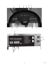
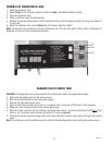
Refer to the photos on the following page for the location of these features.
1. Dispense Switches: Push to dispense product.
2. Stop Switch: Momentary switch stops all dispense functions.
3. Hot Water Switch: Push and Hold switch to dispense hot water from the center dispense tip.
4. Carafe Switch: Momentarily pushed to select the Carafe dispense Volume.
5. Power LED: Red - illuminates when AC power is applied to dispenser.
6. Ready LED: Green - illuminates when the water is at the preset ready temperature.
7. Carafe LED: Yellow - illuminates when the portion dispense option has been selected, (5 second delay).
8. Rinse LED: Yellow - illuminates when the optional preset rinse alarm time has elapsed.
9. Left Refill LED: Yellow - illuminates when the Left Concentrate Can needs replaced.
10. Right Refill LED: Yellow - illuminates when the Right Concentrate Can needs replaced.
11. Function Selector Switch: Allows the user to select different dispensing functions. (Located behind the splash
guard panel)
a. Rinse: Dispenses hot water only- Flushes the mix chamber and dispense tip.
b. Prime: Dispenses concentrates only – Primes the concentrate pump.
c. Normal: Normal dispense mode - Dispenses mixed product (concentrate and water).
12. Mode Selector Switch: Allows the user to select different operating modes.
a. Run: Normal operating position.
b. Night: Anti-pilfering mode that disables dispensing, but keeps heater and chiller operational.
WARNING - The NIGHT Mode does not remove AC power from the dispenser. Disconnect power source before
servicing the dispenser.
c. Program: Enables programming and set up of the dispenser.
13. Programming Switches: Used in conjunction with the LED display to program and calibrate the dispenser to
customer specific requirements.
a. MENU: used to scroll to the next menu screen.
b. (+): used to increase the displayed value.
c. (-): used to decrease the displayed value.
14. LED Display: Displays programming menus and fault messages.
(Continued Next Page)
ELECTRICAL HOOK-UP
CAUTION: Improper electrical installation will damage electronic components.
Refer to Data Plate on the dispenser, and local/national electrical codes to determine circuit requirements.
1. An electrician must provide electrical service as specified in conformance with all local, state and federal
electrical codes.
2. Using a voltmeter, check the voltage and color-coding of each conductor at the electrical source.
3. Connect the dispenser to the power source.
4. If plumbing is to be hooked up later, be sure the dispenser is disconnected from the power source. If plumbing
has been hooked up, the dispenser is ready for Initial Fill & Heat.
39288 070109


