


5
PLUMBING REQUIREMENTS
This dispenser must be connected to a COLD WATER system with operating pressure between 20 and 100 psi (138
and 690 kPa). This water source must be capable of producing a minimum flow rate of 3 fluid ounces (88.7 milliliters) per
second. A shut off valve should be installed in the line before the dispenser. Install a regulator in the line when pressure is
greater than 100 psi (690 kPa) to reduce it to 50 psi (345 kPa). Also if the install location experiences pressure fluctuations
greater than 20 psi (138kPa). The main water inlet is a 3/8” (9.52 mm) male flare.
Additionally, the dispenser’s rinse connection may be connected to a HOT WATER system.
Caution: MAXIMUM RINSE WATER TEMPERATURE: 170 degrees F (76.6 degrees C)
Use BUNN-O-MATIC tubing, part number 34325.10_ _ (see Illustrated Parts Catalog for complete part number) for hot
water connection.
The rinse water operating pressure must be between 20 and 100 psi (138 and 690 kPa). A shut off valve should be
installed in the line before the dispenser. Install a regulator in the line when pressure is greater than 100 psi (690 kPa) to
reduce it to 50 psi (345 kPa). The rinse water inlet is a 3/8” (9.52 mm) barb connection.
NOTE- At least 18 inches (457 mm) of an FDA approved flexible beverage tubing, such as reinforced braided polyethylene,
before the dispenser will facilitate movement to clean the countertop. It can be purchased direct from BUNN-O-MATIC (part
number 34325.10_ _ [see Illustrated Parts Catalog for complete part number.]) BUNN-O-MATIC does not recommend the
use of saddle valves to install the dispenser. The size and shape of the hole(s) made in the supply line(s) by saddle valves
may restrict water flow.
NOTE- On early models dispensers without water inlet valve, a water strainer (Bunn-O-Matic part number 23720.1000)
should be installed in line, prior to the flexible water line. This strainer is supplied loose with the dispenser.
NOTE - Water pipe connections and fixtures directly connected to a potable water supply shall be sized, installed and
maintained in accordance with federal, state and local codes.
This equipment must be installed to comply with the International Plumbing Code of the International
Code Council and the Food Code Manual of the Food and Drug Administration (FDA). For models installed
outside the U.S.A., you must comply with the applicable Plumbing/Sanitation Code for your area.
38218.1 030308
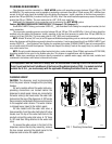
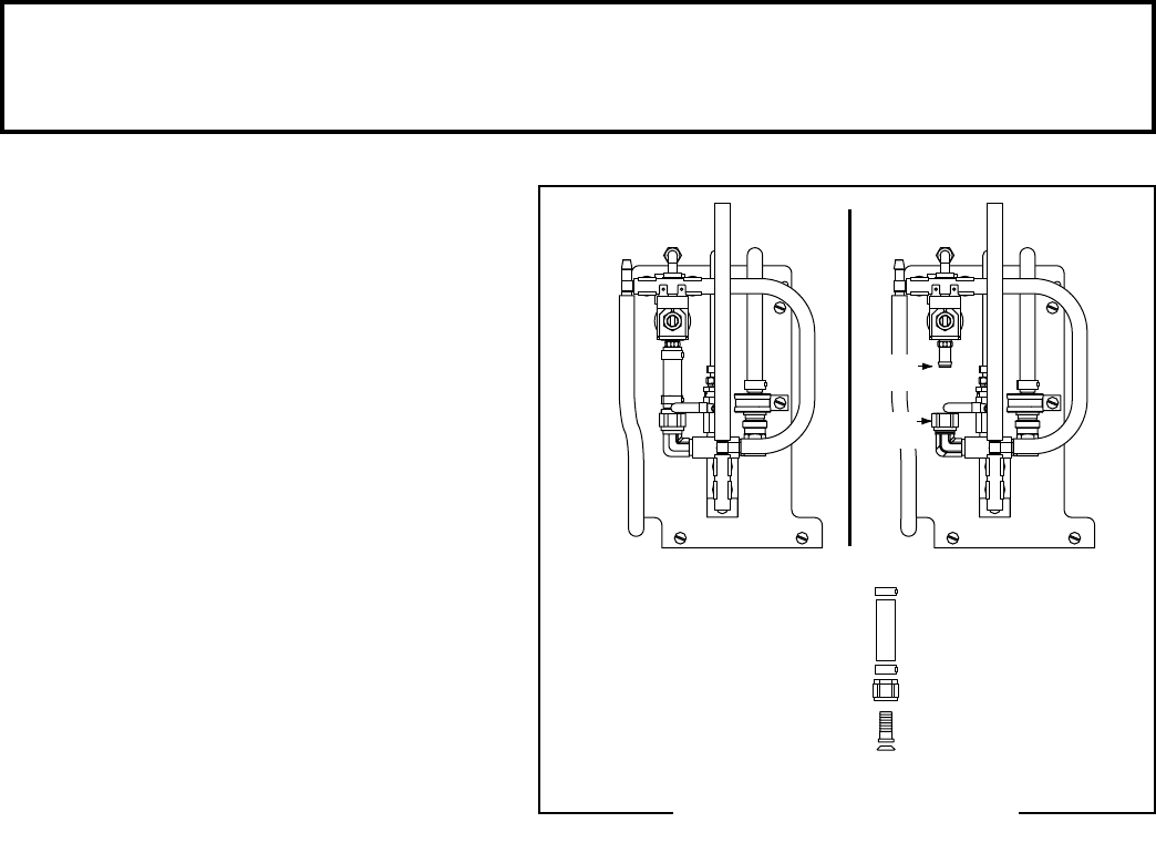
PLUMBING HOOKUP
CAUTION: The dispenser must be disconnected
from the power source throughout the plumbing
hookup.
For early models without the water inlet valve,
plumbing connections are located behind the
dispenser’s splash panel. Hoses are connected to
the water valve(s) and travel under the water bath
tank and out the rear of the dispenser. A .38" female
flare connector is attached to the hose and connects
to the supplied water strainer. The water strainer
is shipped loose, taped to the bottom panel.
For late models with the water inlet valve, a
hose assembly from the water bath shut-off valve
travels over the top of the water bath tank to the
product coil and the water inlet valve. A .75" hose
to .38" male flare fitting attaches to the water inlet
valve.
To access the water valves in the front of the
dispenser, remove the drip tray assembly; remove
the two screws securing the splash panel to the
dispenser and remove the splash panel.
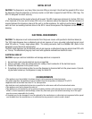
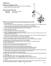
Hot Water Rinse Connection
Hose assembly to be
replaced after Hot Water Rinse
Hot Water
Connection
(See Caution)
Install Cap
with Hot Water
Connection
P2476
FIG 1 Plumbing Connections