


Page 25
SERVICE (cont.)
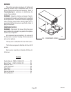
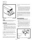
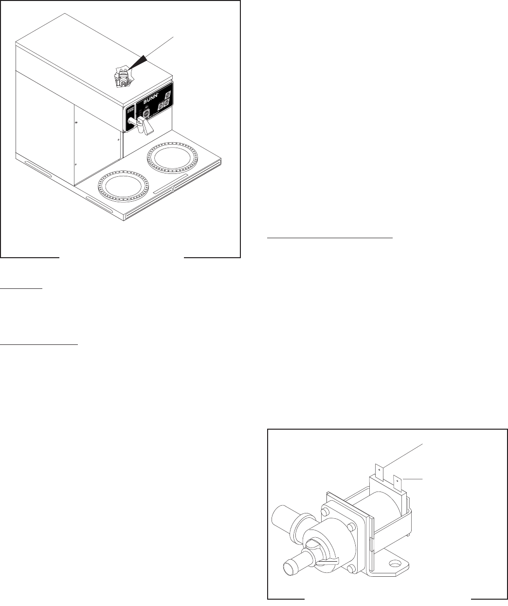
DISPENSE VALVE
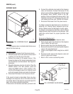
Location:
The dispense valve is located inside the top cover
behind the front end cap.
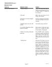
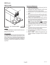
Test Procedures:
1. Disconnect the brewer from the power source.
2. Check the water level in the tank to confirm that it
is within 1/2" from the top of the tank.
3. Connect the brewer to the power source. If the
brewer has been set for brewer temperature lock-
out, this feature must be disabled. See Page 8 for
procedure.
4. Check the dispense valve for coil action. Place the
ON/OFF switch in the "ON" position, press and
release the BREW switch. Listen carefully in the
vicinity of the dispense valve for a "clicking" sound
as the coil magnet attracts and repels the plunger.
5. Disconnect the brewer from the power source.
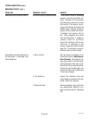
If the sound is heard as described, there may be a
blockage in the dispense valve or the water line to the
sprayhead. Remove the dispense valve and inspect for
wear, and remove waterborne particles.
If the sound is not heard as described, proceed to #6.
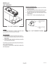
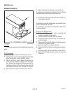
P1852
P1853
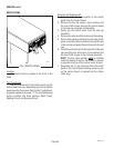
WHI/GRN from
Control Board
WHI from Terminal
Block
FIG. 5 DISPENSE VALVE WIRING
C
A
U
TIO
N
:
WARMERS AND SURFACES ARE HOT
FIG. 4 DISPENSE VALVE
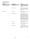
6. Connect the voltmeter lead ends to the dispense
valve coil terminals. Connect the brewer to the
power source. Brewer temperature lockout must
be disabled. Place "ON/OFF" Switch in the "ON"
position. Press and release the brew switch. The
indication must be 120 volts ac for two-wire 120
volt models and three-wire 120/208 volt models.
7. Disconnect the brewer from the power source.
If voltage is present as described, but no coil action is
observed, nor "clicking" heard, dispense valve is de-
fective. Replace valve and test again to verify repair.
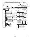
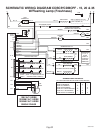
If voltage is not present as described, refer to
Wiring
Diagrams
and check the brewer wiring harness. Also
check the control board for proper operation. See
Page 23.
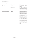
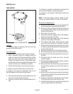
Removal and Replacement:
1. Disconnect wires from the dispense valve.
2. Drain enough water from the tank so the dispense
valve is above the water level.
3. Remove water lines from the dispense valve.
4. Remove the two #8-32 nuts securing the dispense
valve to the sprayhead panel.
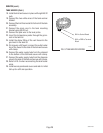
5. Install a new dispense valve using the two #8-32
nuts.
6. Reconnect water lines to the dispense valve and
secure in place with clamps.
7. Refer to FIG. 5 when reconnecting wires.
35582 041503