


Page 14
SERVICE (cont.)
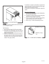
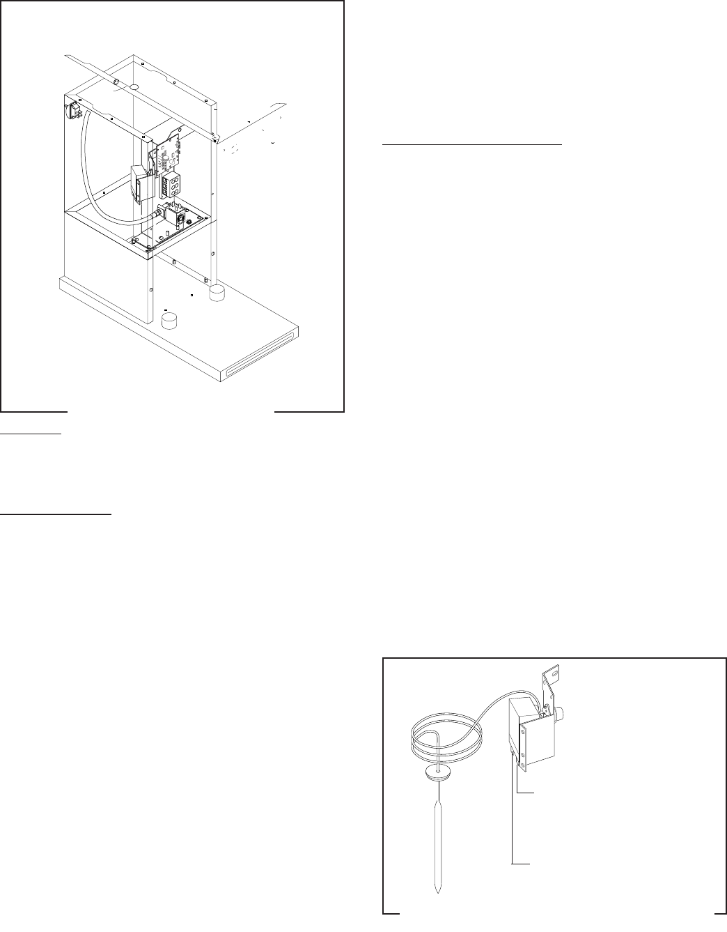
CONTROL THERMOSTAT
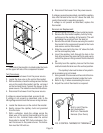
Location:
The control thermostat is located inside the trunk
on the upper left side of the component bracket.
Test Procedures:
1. Disconnect the brewer from the power source.
2. Locate the blue wire on the control thermostat.
3. With a voltmeter, check the voltage across the blue
wire on the control thermostat and the red insert
on the terminal block. Connect the brewer to the
power source. The indication must be 240 volts ac.
4. Disconnect the brewer from the power source.
If voltage is present as described, proceed to #5.
If voltage is not present as described, refer to the
Wiring Diagram
and check the brewer wiring harness.
5. Locate the black wire on the control thermostat.
6. Gently remove the capillary bulb and grommet
from the tank.
7. With a voltmeter, check the voltage across the
black wire of the control thermostat and the red
insert on the terminal block when the control
thermostat is turned "ON" (Fully clockwise). Con-
nect the brewer to the power source. The indica-
tion must be 240 volts ac.
8. Disconnect the brewer from the power source.
If voltage is present as described, reinstall the capillary
tube into the tank to the line 4.5" above the bulb, the
control thermostat is operating properly.
If voltage is not present as described, replace the
thermostat.
Removal and Replacement:
1. Remove wires from control thermostat terminals.
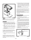
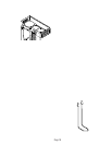
2. Remove the thermostat capillary bulb by firmly
pulling up on the capillary at the tank lid. This will
disengage the grommet from the tank lid.
3. Remove the one #8-32 screw securing the control
thermostat to the component bracket in the trunk
and remove control thermostat.
4. Slide the grommet to the line 4.5" above the bulb
on the new capillary tube.
5. Insert the capillary bulb through the hole in the
tank lid and press the grommet firmly and evenly
so that the groove in the grommet fits into the tank
lid.
6. Carefully bend the capillary tube so that the tube
and bulb inside the tank are in the vertical position.
NOTE - The capillary tube must be clear of any electri-
cal termination and not kinked.
7. Using one #8-32 screw secure the control thermo-
stat to the component bracket inside the trunk.
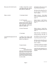
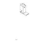
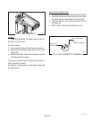
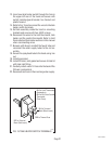
8. Refer to Fig. 3 when reconnecting the wires.
9. Adjust the control thermostat as required.
BLU to Limit Thermo-
stat (Automatics)
BLU from Thermostat
Harness (Pour Overs)
FIG. 3 CONTROL THERMOSTAT TERMINALS
P1469