


Page 23
SERVICE (cont.)
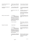
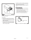
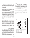
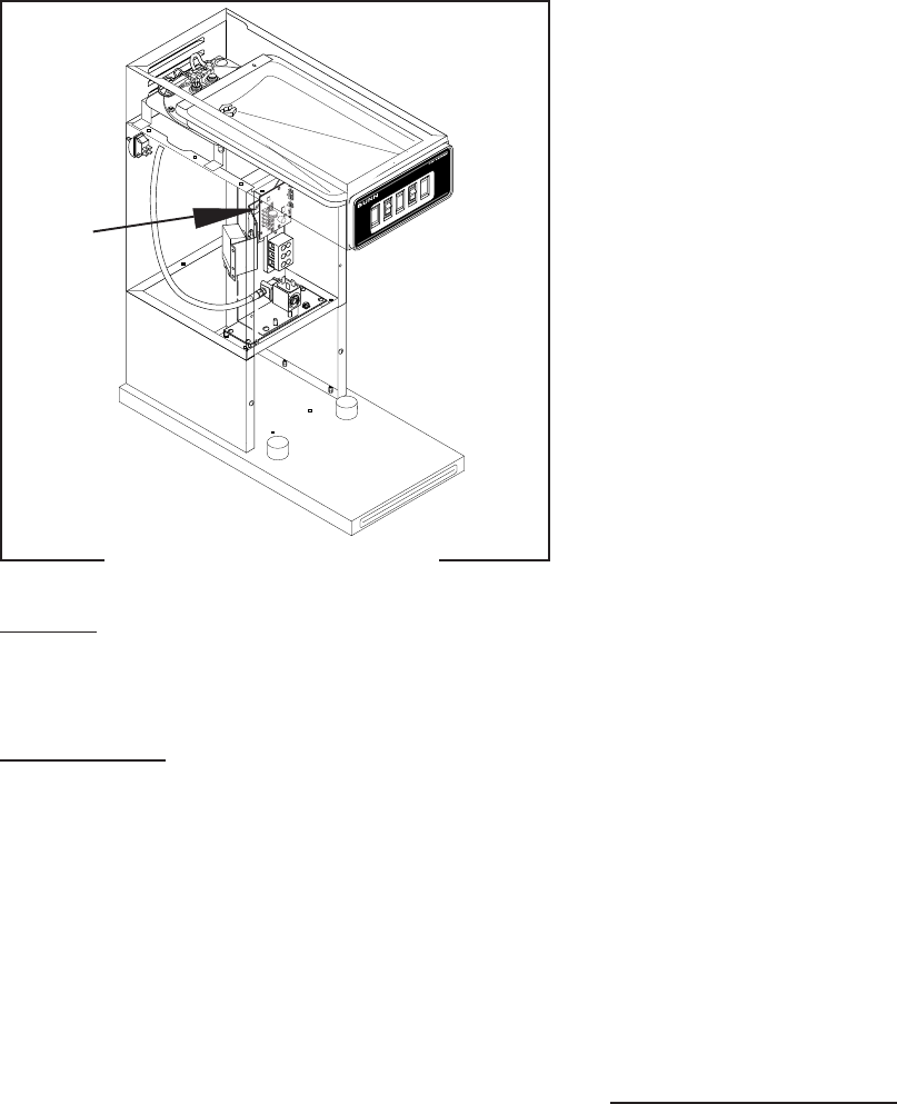
DIGITAL BREW TIMER (Late Models)
P2195.40
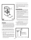
FIG. 18 DIGITAL BREW TIMER
Location:
The timer is located inside the front of the trunk on
the top of the component bracket.
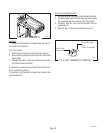
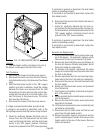
Test Procedure.
NOTE: Do not remove or install wires while timer board
is installed. Pressure applied to one side may cause
damage to the board.
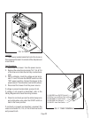
1. Disconnect the brewer from the power source and
remove the front access panel.
2. Remove the two #8-32 screws securing circuit
board to the mounting bracket.
3. Remove circuit board and spacers (as required).
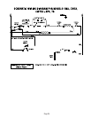
4. With a voltmeter, check the voltage across termi-
nals TL1 and TL2 when the "ON/OFF" switch is in
the "ON" (upper) position. Connect the brewer to
the power source. The indication must be 240
volts ac.
5. Disconnect the brewer from the power source.
If voltage is present as described, proceed to #6.
If voltage is not present as described, refer to the
Wiring Diagram
and check the brewer wiring harness.
6. Disconnect the white/orange wire from terminal
TL3 and the white/yellow wire from terminal TL5.
With a voltmeter, check for continuity across the
two wires when the "ON/OFF" switch is in the "ON"
(upper) position and the START switch is pressed.
Connect the brewer to the power source. The
indication must be 240 volts ac.
If continuity is present as described, reconnect the
wires and proceed to #7.
If continuity is not present as described, refer to the
Wiring Diagram
and check the brewer wiring harness.
7. With a voltmeter, check the voltage across termi-
nals TL1 and TL4 when the "ON/OFF" switch is in
the "ON" (upper) position. Connect the brewer to
the power source. The indication must be 0 volts.
If voltage is as described, proceed to #8.
If voltage is not as described, disconnect the brewer
from the power source and replace the timer.
8. With a voltmeter, check the voltage across termi-
nals TL1 and TL4 when the "ON/OFF" switch is in
the "ON" (upper) position. Connect the brewer to
the power source and press the START switch.
The indication must be as 240 volts ac.
If voltage is present as described, the brew timer is
operating properly. Reset the timer as required, to
obtain the desired brew volume.
If voltage is not present as described, disconnect the
brewer from the power source and replace the timer.
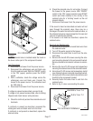
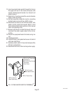
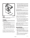
Removal and Replacement:
1. Remove the two #8-32 screws securing circuit
board to the mounting bracket.
2. Remove circuit board and spacers (as required).
3. Remove all wires from the timer.
4. Attach all wires to the replacement timer board
prior to installation to the component mounting
bracket. Refer to FIG. 19 when reconnecting the
wires.
5. Install new circuit board with spacers (as re-
quired) to the component mounting bracket.
6. Adjust the timer as described below.
10690.1 063000