


Page 12
SERVICE
This section provides procedures for testing and
replacing various major components used in this
brewer should service become necessary. Refer to
Troubleshooting
for assistance in determining the
cause of any problem.
WARNING - Inspection, testing, and repair of electri-
cal equipment should be performed only by qualified
service personnel. The brewer should be disconnected
from the power source when servicing, except when
electrical tests are required and the test procedure spe-
cifically states to plug-in the brewer.
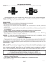
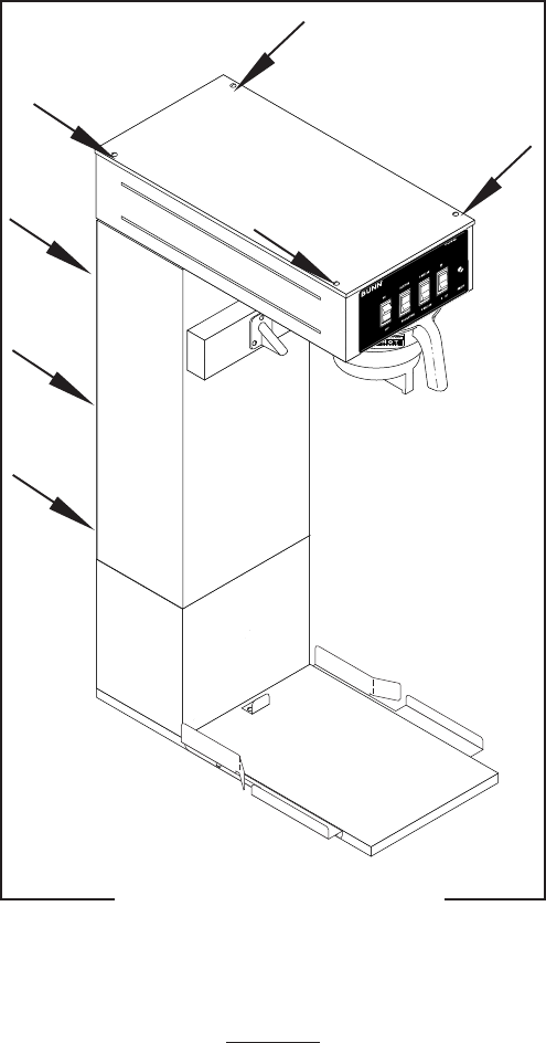
COMPONENT ACCESS
WARNING - Disconnect the brewer from the power
source before the removal of any panel or the replace-
ment of any component.
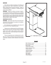
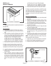
All components are accessible by the removal of
the top cover and rear inspection panel.
The top cover is attached with four #6-32 screws.
Removal of the top cover will allow access to ON/OFF
switch, start switch, batch selector switch, dilution
switch, brew timer, control thermostat, limit thermo-
stat and tank heater.
The rear inspection panel is attached with six #8-
32 screws. Removal of the rear panel will allow access
to the brew solenoid, dilution solenoid and terminal
block.
FIG. 1 COMPONENT ACCESS
P2131.40
10777 041500
Contents
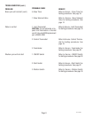
Batch Selector Switch .......................................... 13
Brew Solenoid Valve ............................................ 14
Brew Timer .......................................................... 15
Control Thermostat.............................................. 16
Dilution Solenoid Valve ........................................ 17
Dilution Switch .................................................... 18
Limit Thermostat ................................................. 19
ON/OFF Switch..................................................... 20
Start Switch ......................................................... 21
Tank Heater .......................................................... 22
Wiring Diagram ................................................... 23