


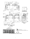
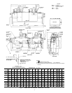
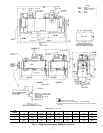
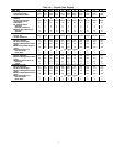
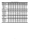
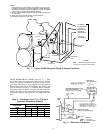
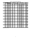
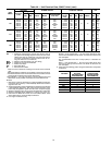
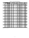
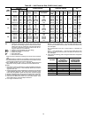
30HXA REFRIGERANT PIPING (See Fig. 7) — Take
care when running the refrigerant piping from the 30HXA
unit to the remote condenser(s) to avoid excessive pres-
sure drops. The pressure drop using R-134a refrigerant is
different than when using R-22 refrigerant. See Tables 2 and
3 for an example fora2F(1.1 C) pressure drop in saturated
temperature in the discharge (hot gas) line and liquid line,
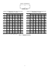
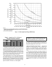
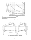
respectively. Refer to Fig. 9 and 10 for line sizing informa-
tion for the discharge and liquid lines for 30HXA (R-134a)
units.
Table 2 — Discharge Line 2 F (1.1 C) Drop in
Saturated Temperature Example
SATURATED
DISCHARGE
TEMP
PRESSURE
R-134a R-22
F C Psig kPa Psig kPa
126 52.2 187.5 1293 281.6 1942
124 51.1 182.0 1255 274.3 1891
⌬ PRESSURE 5.5 38 7.3 51
PRESSURE
RELIEF
DISCHARGE
LINE
LIQUID LINE
LIQUID LINE
ANGLE
VALVE
OIL
SEPARATOR
COOLER*
TO REMOTE
CONDENSER(S)
TO REMOTE
CONDENSER(S)
TO REMOTE
CONDENSER(S)
TO REMOTE
CONDENSER(S)
EXV
EXV
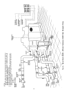
Fig.7—Typical 30HXA Refrigerant Piping to Remote Condenser
NOTES:
1. Piping shown is for general point-of-connection only and is not in-
tended to show details for a specific installation. Certified field wir-
ing anddimensional drawings areavailable uponrequest. The30HXA
units should be installed using certified drawings.
2. Refer to Carrier System Design Manual for details regarding pip-
ing techniques.
3. Piping and pressure relief devices are field supplied.
4. Vent pipes properly per local codes.
LEGEND
EXV — Electronic Expansion Valve
*See Fig. 6 for typical cooler piping.
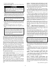
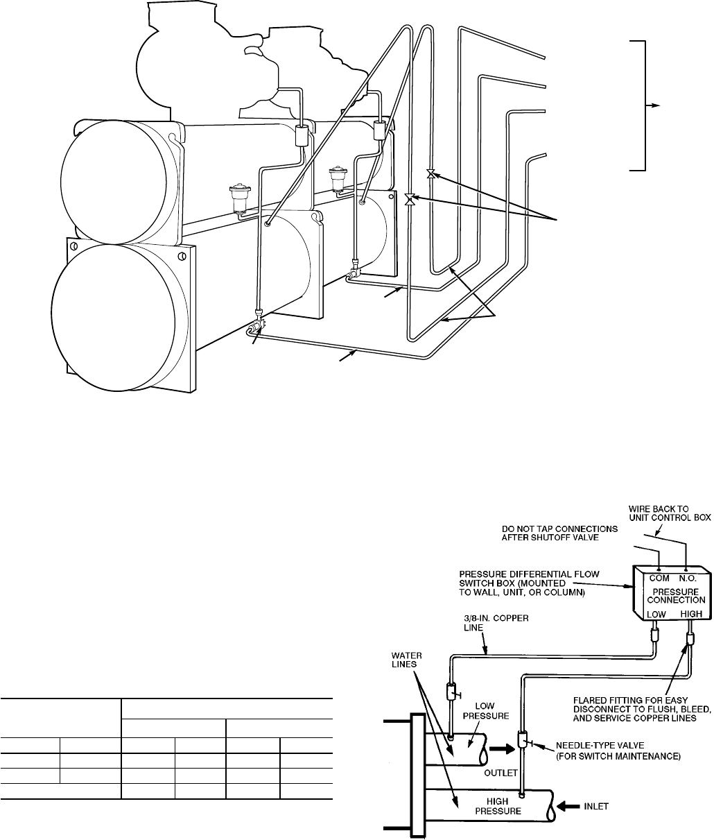
LEGEND
COM — Common
N.O. — Normally Open
Fig. 8 — Differential Flow Switch
11