


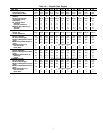
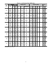
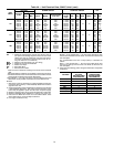
Table 1A — Physical Data, English
UNIT SIZE 076 086 096 106 116 126 136 146 161 171 186
UNIT WEIGHT (lb)
Fluid Cooled (HXC) 5700 5723 5855 6177 6415 6465 6688 6718 7452 7660 7854
Condenserless (HXA) 4717 4744 4835 5151 5162 5205 5308 5333 5752 5777 5946
COMPRESSORS Semi-Hermetic, Twin Screw
Quantity 222222 2 2 2 2 2
Nominal Capacity per
Compressor (tons)
39/39 46/39 56/39 66/39 66/46 66/56 80/56 80/66 80/56 66/80 80/80
Economizer No No No No No No No No Yes Yes Yes
No. Capacity Steps
Standard 666666 6 6 6 6 6
Optional (maximum) 888888 8 8 8 8 8
Minimum Step Capacity (%)
Standard 20 20 20 20 20 20 20 20 20 20 20
Optional 10 10 10 10 10 10 10 10 10 10 10
REFRIGERANT TYPE R-134a
Charge* (lb)
55/55 66/55 79/55 95/55 95/66 95/79 114/79 114/95 130/90 109/130 130/130
Circuit A/Circuit B
COOLER TYPE Shell and Tube with Enhanced Copper Tubes
Part No. 10HX400− 001 001 002 010 007 007 006 006 104 012 013
Net Fluid Volume (gal) 17.0 17.0 19.0 22.6 21.4 21.4 24.0 24.0 28.5 28.5 33.4
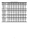
Maximum Refrigerant Pressure
(psig)
220 220 220 220 220 220 220 220 220 220 220
Maximum Fluid-Side Pressure
(psig)
300 300 300 300 300 300 300 300 300 300 300
Fluid Connections (in.) Steel Weld Couplings
Inlet and Outlet 444544 4 4 5 5 5
Drain (NPT)
1
⁄
2
1
⁄
2
1
⁄
2
1
⁄
2
1
⁄
2
1
⁄
2
1
⁄
2
1
⁄
2
1
⁄
2
1
⁄
2
1
⁄
2
30HXA OIL SEPARATOR
Part No. 09RX400− 007 007 008 008 009 009 009 009 009 010 010
Maximum Refrigerant Pressure
(psig)
320 320 320 320 320 320 320 320 320 320 320
Refrigerant Connections (in.)
Discharge 2
1
⁄
8
2
1
⁄
8
2
1
⁄
8
2
1
⁄
8
2
1
⁄
8
2
1
⁄
8
2
1
⁄
8
2
1
⁄
8
2
1
⁄
8
2
1
⁄
8
2
1
⁄
8
Liquid 1
1
⁄
8
1
1
⁄
8
1
1
⁄
8
1
1
⁄
8
1
1
⁄
8
1
1
⁄
8
1
1
⁄
8
1
1
⁄
8
1
3
⁄
8
1
3
⁄
8
1
3
⁄
8
CONDENSER (HXC) Shell and Tube with Enhanced Copper Tubes
Part No. 09RX400− 001 001 002 002 003 003 004 004 005 006 006
Net Fluid Volume (gal) 16.8 16.8 18.3 18.3 23.9 23.9 27.5 27.5 30.6 37.6 37.6
Maximum Refrigerant Pressure
(psig)
220 220 220 220 220 220 220 220 220 220 220
Maximum Water-Side Pressure
(psig)
300 300 300 300 300 300 300 300 300 300 300
Water Connections (in.) Steel Weld Couplings
Inlet and Outlet 555555 5 5 5 5 5
Drain (NPT)
1
⁄
2
1
⁄
2
1
⁄
2
1
⁄
2
1
⁄
2
1
⁄
2
1
⁄
2
1
⁄
2
1
⁄
2
1
⁄
2
1
⁄
2
*Charges listed are for 30HXC units. The 30HXA units are shipped with a holding charge only.
7