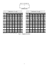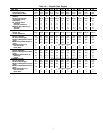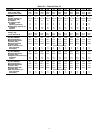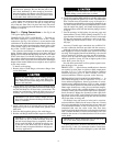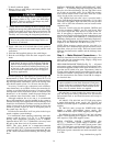
To install condenser piping:
1. Remove bolts on weld flanges, and remove flanges from
condenser water heads.
Remove the weld flanges before welding piping to
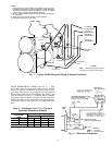
the flanges. Refer to Fig. 1 and 2 for weld flange
locations. Failure to remove the flanges may dam-
age the sensors and insulation.
2. To keep debris from entering the heat exchanger during
shipping and storage, the gaskets between the weld flanges
and the water heads do not have holes cut into them. The
gaskets have perforations where the holes are to be cut.
Carefully cut a hole along the designated perforations.
IMPORTANT: Be sure to remove flanges and cut
holes in the gaskets between the flanges and the wa-
ter heads as indicated.
3. Apply a thin coat of oil to both sides of each gasket to
help ensure a good seal, and reattach each gasket to each
water head.
4. Weld the field-supplied piping to the weld flanges.
5. Bolt the weld flanges back onto their respective water
heads.
IMPORTANT: When bolting the weld flanges to the
water heads, be sure to locate the flange such that
the hole in each flange lines up completely with the
hole in each water head. If installed incorrectly, part
of the hole in the water head will be blocked off.
This will result in impaired water flow in high pres-
sure drop applications.
Provide openings in water piping for pressure gages and
thermometers (if used). These openings should be 5 to 10
pipe diameters from the unit water nozzles. For thorough mix-
ing and temperature stabilization, wells in the leaving water
pipe should extend at least 2 in. (50 mm) into the pipe.
Accessory Victaulic-type connections and condenser-
water thermistors are available. Follow the connection di-
rections as provided with the accessory. If accessory differ-
ential pressure switch, water flow switch, or condenser water
thermistor is to be installed, install the proper fittings into
the condenser water lines before water is connected.
Although condenser has an air vent, it is recommended
that a field-supplied air vent be installed in the system to
facilitate servicing. Field-supplied shut-off and balancing valves
should also be installed to facilitate servicing and flow bal-
ancing. Locate valves in inlet and outlet lines as close to the
chiller as possible. Locate air vents at the highest point of
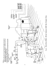
the system loop. See Fig. 6.
Provide drain connections at all low points in the loop to
permit complete system drainage.
For installations where entering condensing water tem-
perature could be below 70 F (21 C), a field-supplied
leaving water temperature regulating valve is required.
Operation below 70 F (21.1 C) without this valve may cause
the unit to shut down on low oil pressure alarms.
NOTE: This valve should be a temperature-controlled
valve (DO NOT USE a pressure-controlled valve) which
controls to 80 F (26.7 C) leaving water temperature. Be sure
to add a bleed line between the entering and leaving water
lines.
INSTALL PRESSURE RELIEF REFRIGERANT VENT
PIPING — To facilitate refrigerant vent piping, units have
flares for all of the relief fittings. The low side relief valves
on all units are provided with a 3/4 in. NPT flare connec-
tions, and are located on the cooler shell. There are 2 relief
valves for the cooler; one on each circuit.
The 30HXA high side relief valve is provided with a
5/8 in. SAE (Society of Automotive Engineers, U.S.A.) flare
connection. The 30HXC high side relief valves are provided
with a 3/4 in. NPT flare connection, and are located on the
condenser shell.
There are 2 relief valves for the separator (30HXA) and
2 for the condenser (30HXC); one for each circuit. Most
local codes require that these devices be piped to the out-
side. If vent piping is required by local codes, these con-
nections have been provided to aid in the connection of vent
piping in accordance with ASHRAE 15 (American Society
of Heating, Refrigeration, and Air Conditioning Engineers),
Safety Code for Mechanical Refrigeration. If vent piping is
required, do not restrict the vent flow in any way.
NOTE: When accessory suction service valve kit is in-
stalled, there are 2 additional high-side pressure relief valves.
Pipe these valves per local codes. These are located on the
discharge line between the muffler and the discharge shut-
off valve.
Step 4 — Make Electrical Connections — The
electrical characteristics of the available power supply must
agree with the unit nameplate rating. Supply voltage must
be within the limits shown.
FIELD POWER CONNECTIONS (See Fig. 12) — All power
wiring must comply with applicable local and national codes.
Install field-supplied, branch circuit fused disconnect(s) of a
type that can be locked off or open. Disconnect(s) must be
located within sight and readily accessible from the unit in
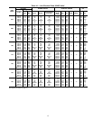
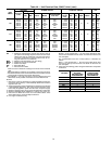
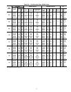
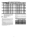
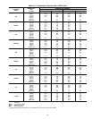
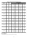
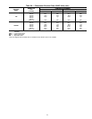
compliance with NEC Article 440-14. See Tables 4A and 4B
for unit electrical data. See Tables 5A and 5B for compres-
sor electrical data.
IMPORTANT: the 30HX units have a factory-installed
option available for a non-fused disconnect for unit power
supply. If the unit is equipped with this option, all field
power wiring should be made to the non-fused discon-
nect since no terminal blocks are supplied.
All units have a single location for power entry to sim-
plify the field power wiring. Maximum wire size that the
unit terminal block or non-fused disconnect will accept is
500 kcmil.
All 380/415-3-50, 460-3-60, and 575-3-60 units require
a single field-supplied power supply. All 230-3-50 and
208/230-3-60 units require 2 separate field-supplied power
supplies.
All 380-3-60 units (except the 30HXC/A186 units)
require a single field-supplied power supply. The
30HXC/A186 units require 2 field-supplied power supplies.
The 30HXA136-186 and 30HXC171,186, 346-3-50 units
require 2 field-supplied power supplies. All other 346-3-50
units require a single field-supplied source.
FIELD CONTROL POWER CONNECTIONS (See
Fig. 13) — Units with a power supply of 208/230-, 460-,
and 575-3-60 require 115-1-60 control circuit power. Units
with a 380-3-60 power supply require 230-1-60 control cir-
cuit power. All other units 230-1-50 control circuit power.
Field control power connections are made at terminals 1 and
2 of TB4.
Copy continued on page 26.
14


